Glass transition temperature (Tg) - A210
| Glass transition temperature (Tg) | |
|---|---|
| Foundational knowledge article | |

| |
| Document Type | Article |
| Document Identifier | 210 |
| Themes | |
| Relevant Class |
Material |
| Tags | |
| Prerequisites | |
Introduction[edit | edit source]
Glass transition represents the temperature region where a polymer behaviour transitions from a hard-glassy material, to that of a soft rubbery material. At this temperature point (more correctly over a temperature range or region), a sudden loss in mechanical stiffness occurs.
Scope[edit | edit source]
This page defines polymer glass transition temperature (Tg) and explains its significance to composites processing. Typical values for glass transition of various polymer matrices are provided, along with a brief introduction to measurement techniques.
Significance[edit | edit source]
The glass transition temperature (Tg) of a polymer is critical for defining its operating temperature limits. At temperatures above Tg, a polymer experiences a sudden drop in its mechanical stiffness.
Typically, when mechanical stiffness is desired, a polymer’s service temperature should be below its Tg. However, in applications where flexibility is desired, the polymer should be in service about its Tg temperature. An example of this latter case is utilizing the flexibility provided by rubbers and elastomers.
Prerequisites[edit | edit source]
Recommended documents to review before, or in parallel with this document:
Definition[edit | edit source]
Polymers are classified as glassy when their molecular backbones exhibit the inability to move and remain “frozen” in crumpled immobile conformations. Below the glass transition temperature (Tg), upon heating only thermally induced expansion between the molecules occurs. Above Tg, amorphous regions within the polymer observe liquid-like “flow” with the molecular chains gaining rapid ability to move freely, while crystalline regions remain locked in the glassy state configuration.
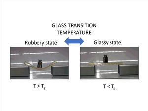
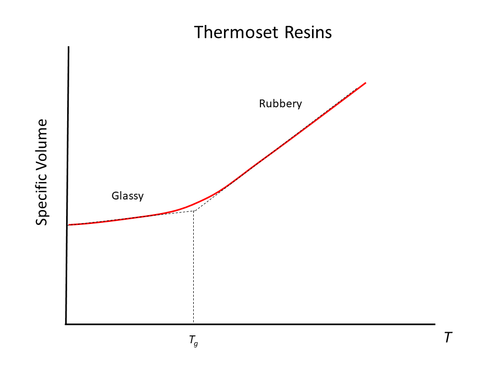
As an outcome of this behavioral transition, a polymer exhibits a sudden change in its specific volume to temperature response (thermal expansion) at its Tg transition. Mechanically, a softening drop in mechanical stiffness occurs. This substantial drop in mechanical stiffness is shown in the example picture, showing a polymer below and above its glass transition temperature.
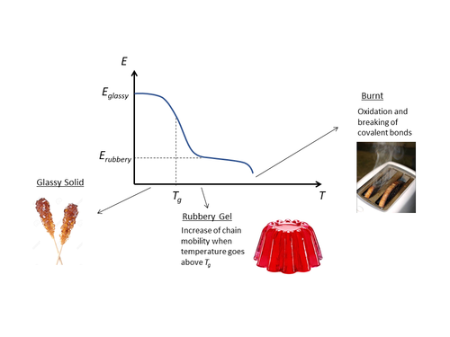
At temperatures above Tg, a substantial reduction in Young’s Modulus (E) is observed between the stiff glassy state and the softened rubbery state. To ensure in service mechanical stiffness of the polymer, the operational temperature should be below Tg. However, there are situations where having the service temperature above the polymer’s Tg to obtain rubbery behaviour is intended. Elastomers are the classic example, where their rubbery behaviour is desired and the material is used above its Tg.
Typical Property Values[edit | edit source]
| Polymer | Glass transition temperature | Source | |
|---|---|---|---|
| (°C) | (°F) | ||
| Thermoset polymers | |||
| Epoxy | 150-265 | 302-509 | [1] |
| Phenolic | 127-159 | 261-318 | [1] |
| Polymide | 320-330 | 608-626 | [1] |
| BMI | 294-300 | 561-572 | [1] |
| Cyanate | 230-265 | 446-509 | [1] |
| Thermoplastic polymers | |||
| Polyamide-imide (PAI) | 275 | 527 | [1] |
| Polyaryl ethers | 220-260 | 428-500 | [1] |
| Polyether sulphone (PES) | 220 | 428 | [1] |
| Polyether-imide (PEI) | 210 | 410 | [1] |
| Polyarylene sulfide (PAS) | 200-210 | 392-410 | [1] |
| Polyetherether ketone (PEEK) | 140-145 | 284-293 | [1] |
| Polyphenylene sulfide (PPS) | 85-95 | 185-203 | [1] |
| Polyarylene ketone | 200-210 | 392-410 | [1] |
| Polyimide (PI) | 250-280 | 482-536 | [1] |
Measurement[edit | edit source]
The glass transition temperature (Tg) of a polymer can be measured using several different laboratory techniques. Each method relies on a different measurement principle, resulting in slight differences of determined Tg between the methods.
Common laboratory techniques to measure Tg include:
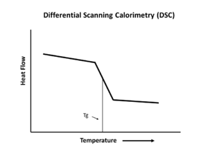
- Differential Scanning Calorimetry (DSC) – measures heat flow changes
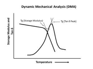
- Dynamic Mechanical Analysis (DMA) – measures behavioural change in mechanical stiffness
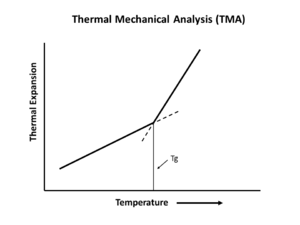
- Thermal Mechanical Analysis (TMA) – measures volume changes
| Characterization Method | Example Data | Measurement Notes | (How to) KPC Method Document |
|---|---|---|---|
| Differential Scanning Calorimetry (DSC) | A heat flow change is observed in the region of Tg. An advantage to DSC is that only a small sample size is required (milligrams). | Method document coming soon. | |
| Dynamic Mechanical Analysis (DMA) | At Tg, the storage modulus (G' or E') drops by several orders of magnitude. Two properties are normally reported; tosional (G'), bending (E') stiffness and loss tangent (tan \(\delta\)). | Method document coming soon. | |
| Thermal Mechanical Analysis (TMA) | Slope thermal expansion vs. temperature experiences changes at Tg. | Method document coming soon. |
Related pages
References
- ↑ 1.00 1.01 1.02 1.03 1.04 1.05 1.06 1.07 1.08 1.09 1.10 1.11 1.12 1.13 1.14 [Ref] Pilato, Louis A.; Michno, Michael J. (1994). Advanced Composite Materials. Springer-Verlag Berlin Heidelberg. doi:10.1007/978-3-662-35356-1. ISBN 978-3-540-57563-4.CS1 maint: uses authors parameter (link) CS1 maint: date and year (link)
| About | Help |
Welcome
Welcome to the CKN Knowledge in Practice Centre (KPC). The KPC is a resource for learning and applying scientific knowledge to the practice of composites manufacturing. As you navigate around the KPC, refer back to the information on this right-hand pane as a resource for understanding the intricacies of composites processing and why the KPC is laid out in the way that it is. The following video explains the KPC approach:
Understanding Composites Processing
The Knowledge in Practice Centre (KPC) is centered around a structured method of thinking about composite material manufacturing. From the top down, the heirarchy consists of:
- The factory
- Factory cells and/or the factory layout
- Process steps (embodied in the factory process flow) consisting of:
The way that the material, shape, tooling & consumables and equipment (abbreviated as MSTE) interact with each other during a process step is critical to the outcome of the manufacturing step, and ultimately critical to the quality of the finished part. The interactions between MSTE during a process step can be numerous and complex, but the Knowledge in Practice Centre aims to make you aware of these interactions, understand how one parameter affects another, and understand how to analyze the problem using a systems based approach. Using this approach, the factory can then be developed with a complete understanding and control of all interactions.
Interrelationship of Function, Shape, Material & Process
Design for manufacturing is critical to ensuring the producibility of a part. Trouble arises when it is considered too late or not at all in the design process. Conversely, process design (controlling the interactions between shape, material, tooling & consumables and equipment to achieve a desired outcome) must always consider the shape and material of the part. Ashby has developed and popularized the approach linking design (function) to the choice of material and shape, which influence the process selected and vice versa, as shown below:
Within the Knowledge in Practice Centre the same methodology is applied but the process is more fully defined by also explicitly calling out the equipment and tooling & consumables. Note that in common usage, a process which consists of many steps can be arbitrarily defined by just one step, e.g. "spray-up". Though convenient, this can be misleading.
Workflows
The KPC's Practice and Case Study volumes consist of three types of workflows:
- Development - Analyzing the interactions between MSTE in the process steps to make decisions on processing parameters and understanding how the process steps and factory cells fit within the factory.
- Troubleshooting - Guiding you to possible causes of processing issues affecting either cost, rate or quality and directing you to the most appropriate development workflow to improve the process
- Optimization - An expansion on the development workflows where a larger number of options are considered to achieve the best mixture of cost, rate & quality for your application.
To use this website, you must agree to our Terms and Conditions and Privacy Policy.
By clicking "I Accept" below, you confirm that you have read, understood, and accepted our Terms and Conditions and Privacy Policy.

