Practice for Developing a Demoulding Step - P159
| Practice for Developing a Demoulding Step | |||||||
|---|---|---|---|---|---|---|---|
| Practice document | |||||||

| |||||||
| Document Type | Practice | ||||||
| Document Identifier | 159 | ||||||
| Themes | |||||||
| Tags | |||||||
| Objective functions |
| ||||||
| MSTE workflow | Development | ||||||
| Prerequisites | |||||||
Overview[edit | edit source]
This page will provide guidance into what to consider for developing a demoulding step. The page is broken into the main considerations of Material, Shape, Tooling and Equipment (MSTEP). Material and shape will, for the most part, be decided at this point in the manufacturing process, but developing this process step will provide some insight into what to consider for your part's material and shape design choices. Considerations for demoulding should be made in terms of shape and tooling to ensure successful demoulding. The tooling, consumables and equipment will be where you will have the most to consider when developing the demoulding step, as there are many options and techniques that will depend on your process and part.
Introduction[edit | edit source]
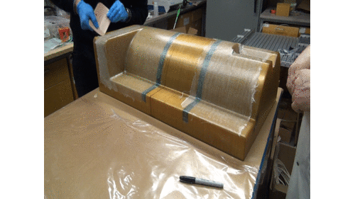
Demoulding a composite part is when the part is fully or partially cured and ready to be taken off the tool. This is the first time the part will be able to hold its own shape and begin to resemble the final product. This is an important step in the production of composite parts because the final shape and quality of the part can be affected by the demoulding process. Damage can be induced in the part during demoulding. Developing a robust procedure for demoulding will prevent damage to the part and also reduce production time and cost. The quality of the demoulding process can impact the overall quality of the composite part, so it is important to take care during this step of the manufacturing process. A successful demoulding process can help ensure that the final product is of high quality, with the correct shape and dimensions, and without any visible defects.
Practice[edit | edit source]
The majority of demoulding development should be concentrated during the tooling design, layup, and tool preparation stages. It is vital to prioritize the part's demoulding process as part of the tool design process. Simplicity is key when designing the tool, so it should be kept as straightforward as possible. In cases where the part design involves negative draft angles or sharp radii, it may be necessary to utilize a multi-segmented mould or secondary bonding of two composite pieces rather than overcomplicating the tooling system. Ultimately, the tool design should simplify the demould process, reducing the amount of time and effort spent on demoulding. With that in mind, the following sections provide insight into what to consider when developing a demoulding step for your part.
Material[edit | edit source]
When considering the effects of material in a demoulding step, we will mostly be concerned with the development of residual stresses in the material and how that can impact the demoulding process. Residual stresses can lead to the part deforming or wanting to deform after the part has cured. This can be in the form of springing in so the part clamps into the tool and becomes challenging to remove, or that the part springs away from the tool and can suddenly release when removing the consumables. To read more about managing residual stress, see Residual stress and dimensional control management (RSDM)
Shape[edit | edit source]
The majority of the shape considerations, including draft angle and die-lock, are available in the Shape Development page.
Tooling[edit | edit source]
A mould release agent can help to prevent the composite part from sticking to the mould. Apply the release agent according to the manufacturer's instructions before laying up the composite. Apply the release agent in multiple thin layers, allowing each layer to dry completely before applying the next. This can help to ensure that the release agent provides complete coverage and helps to prevent the composite from sticking to the mould Or Use a release film. A release film can be used between the mould surface and the composite material to help prevent excess resin from flowing out of the material during curing.
When removing a composite part from the mould tool, it is important to remove any ancillary materials, such as peel ply, tapes, and part dams, as part of the initial steps in the demoulding process. Failing to remove these materials can cause complications and increase the risk of injury and/or damage. For example, if the peel ply is not removed before the part is demoulded, it may become stuck to the part and be difficult to remove, leading to damage to the part or even causing it to be scrapped. Additionally, by removing tapes or part dams prior to demoulding, the chance of being cut by a part's edge before deburring can be mitigated, making the overall process safer and more efficient.
Equipment[edit | edit source]
Demould Aids[edit | edit source]
Use of non-metallic tool, such as a plastic wedge or spatula, to gently pry the part away from the mould is common. With this process, be mindful of draft angles and the possibility of fiber damage within the laminate. Do not use excessive force. If the part does not easily come up from hand pressure, place additional shims into the area until the part frees from the mould. Avoid using metal tools as they could damage the composite and the tool. If the tool is scratched or otherwise damaged, the damage will show up on the subsequent parts that are produced. Meaning the tool will need to be repaired before being used again.
An air gun can be used to blow air in between the part and the tool once the wedges are set to provide some additional separation of the tool and part.
Rubber mallets may also be used with caution to force the non-metallic wedges into the gaps.
Heat Gun: Apply a moderate amount of heat: If the part is still difficult to remove, you can try applying heat to the mould. Use a heat gun or a hair dryer to warm the mould slightly. This should help to loosen the part and make it easier to remove.
HSE[edit | edit source]
Gloves, eye protection, parts may be hot It is highly recommended to wear cut-resistant gloves when demoulding composites, as the edges caused by resin flash and stray fibres are often sharper than typical knife blades found in a household. Even a small cut can require stitches. In addition, it is crucial to wear appropriate eye protection as chips of resin can be expected to fly out and potentially cause injury to the eyes.
Composites are either cured at room temperature, or elevated temperatures with equipment such as an oven or an autoclave. All of these processes will cause the tool and part to heat up, so it is important to let the system cool before demoulding. It is important to ensure that the part is below Tg to avoid warpage.
Resin Flash and Sharp Edges[edit | edit source]
As previously mentioned, the edges of a composite part, including any resin flash, can be sharp and pose a potential hazard. To address this issue, a fine grit sandpaper or deburring tool can be used to carefully sand the edges and remove any excess resin or stray fibers. It is important to note that, depending on the design of the part, there may be up to an inch of excess material around the edge that will be removed in a later step, so the edge sanding process need not be overly precise. Nevertheless, it is critical to exercise caution when sanding the edges to avoid damaging the center of the part. By taking these measures, the edges can be smoothed out and any sharpness can be eliminated, making the composite part safer to handle and work with.
Qualification, Commissioning and Approval[edit | edit source]
| About | Help |
Welcome
Welcome to the CKN Knowledge in Practice Centre (KPC). The KPC is a resource for learning and applying scientific knowledge to the practice of composites manufacturing. As you navigate around the KPC, refer back to the information on this right-hand pane as a resource for understanding the intricacies of composites processing and why the KPC is laid out in the way that it is. The following video explains the KPC approach:
Understanding Composites Processing
The Knowledge in Practice Centre (KPC) is centered around a structured method of thinking about composite material manufacturing. From the top down, the heirarchy consists of:
- The factory
- Factory cells and/or the factory layout
- Process steps (embodied in the factory process flow) consisting of:
The way that the material, shape, tooling & consumables and equipment (abbreviated as MSTE) interact with each other during a process step is critical to the outcome of the manufacturing step, and ultimately critical to the quality of the finished part. The interactions between MSTE during a process step can be numerous and complex, but the Knowledge in Practice Centre aims to make you aware of these interactions, understand how one parameter affects another, and understand how to analyze the problem using a systems based approach. Using this approach, the factory can then be developed with a complete understanding and control of all interactions.
Interrelationship of Function, Shape, Material & Process
Design for manufacturing is critical to ensuring the producibility of a part. Trouble arises when it is considered too late or not at all in the design process. Conversely, process design (controlling the interactions between shape, material, tooling & consumables and equipment to achieve a desired outcome) must always consider the shape and material of the part. Ashby has developed and popularized the approach linking design (function) to the choice of material and shape, which influence the process selected and vice versa, as shown below:
Within the Knowledge in Practice Centre the same methodology is applied but the process is more fully defined by also explicitly calling out the equipment and tooling & consumables. Note that in common usage, a process which consists of many steps can be arbitrarily defined by just one step, e.g. "spray-up". Though convenient, this can be misleading.
Workflows
The KPC's Practice and Case Study volumes consist of three types of workflows:
- Development - Analyzing the interactions between MSTE in the process steps to make decisions on processing parameters and understanding how the process steps and factory cells fit within the factory.
- Troubleshooting - Guiding you to possible causes of processing issues affecting either cost, rate or quality and directing you to the most appropriate development workflow to improve the process
- Optimization - An expansion on the development workflows where a larger number of options are considered to achieve the best mixture of cost, rate & quality for your application.
To use this website, you must agree to our Terms and Conditions and Privacy Policy.
By clicking "I Accept" below, you confirm that you have read, understood, and accepted our Terms and Conditions and Privacy Policy.


