Use of Right Sized Simulation to Aid Decision Making in Thermoplastic Composite Manufacturing Systems - C114
| Use of Right Sized Simulation to Aid Decision Making in Thermoplastic Composite Manufacturing Systems | |||||||
|---|---|---|---|---|---|---|---|
| Case study | |||||||

| |||||||
| Document Type | Case study | ||||||
| Document Identifier | 114 | ||||||
| Tags | |||||||
| Objective functions |
| ||||||
| MSTE workflow | Development | ||||||
| Prerequisites | |||||||
Summary[edit | edit source]
This case study explores the implementation of right-sized simulation techniques to optimize decision-making in the manufacturing of Thermoplastic polymers. The case study examines a novel guardrail system designed to be manufactured by continuously hot-rolled thermoplastic and fiberglass composite, highlighting the critical nature of maintaining specific environmental conditions during manufacturing to prevent defects and ensure the structural integrity of the final product. The case study study underscores the potential of simulation tools in reducing risks and enhancing the manufacturability and performance of complex composite structures.
Introduction[edit | edit source]
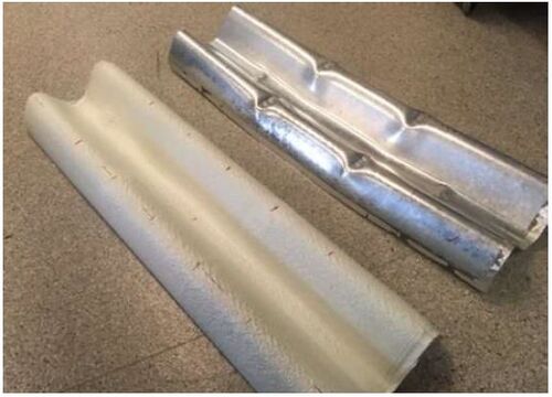
Composite materials offer many advantages for the manufacture of advanced structures in fields such as aerospace, transportation, marine and commodity products. As such a tailorable material, with respect to properties and performance, composites are quite attractive to right-size products for their specific application [1]. Likewise, being able to shape a material at the same time as developing its material properties poses many cost and time advantages, by reducing the total number of manufacturing steps required. However, this can have drawbacks too. By taking so many actions at once, it is also possible to more easily make one wrong decision and end up with an suboptimal composites structure. For example, an industrial partner is working in the field of transportation infrastructure, looking to manufacture continuously hot-rolled thermoplastic and fiberglass composite guardrails for automobiles. The figure below illustrates the geometry of the guardrail system being considered.
Linked with the aforementioned issues of composites manufacturing, the fiberglass and polypropylene (PP) composite guardrail poses similar issues. Guardrails have important dimensional tolerances, so that they can effectively be assembled into a reliable and repeatable structural system, without the aid of shimming or other fitting methods that may compromise structural performance. Similarly, the structural performance itself is highly critical, as the energy absorption of the guardrail structure is what ultimately dampens the kinetic energy of an uncontrolled vehicle, to ideally bring it to a steady and controlled stop and prevent the injury of the vehicle’s occupants, or other people in the area. A schematic of the manufacturing process is briefly shown below, demonstrating how the spools of continuous comingled material are unwound into convection ovens and progressively rolled into shape.
Designing the process, such that the woven composite material has specific temperatures at specific points in the rolling process, is critical. By deviating from these requirements, the product may have residual stresses formed with it, as well as associated geometrical defects, which can present itself as severely as experiencing cracking and failure during the manufacturing process. Learn more about residual stress and dimensional control here. It is desirable for the materials to be formed at the right time; not too soon after exiting the oven that it will remain soft and deform, nor should it be too long after exiting the oven when it is hard and unable to properly form.
Approach[edit | edit source]
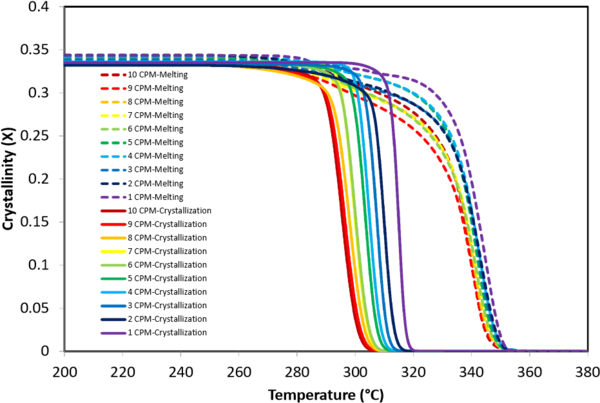
With composites, it is as important to design the manufacturing process as it is to design the structure itself, keeping the MSTEP systems approach to composites in mind. This means characterizing the materials being used and understanding how the material properties develop under temperature over time. For the materials being used in the guardrail, as a thermoplastic, understanding the material relative crystallinity (RC) is the major factor of importance in a cooling-based process such as continuous roll-forming [2][3]. As such, it is important to capture how the material RC develops when being rolled through the manufacturing system, where it is desirable for the final shape to be obtained at a specific point in the RC development curve. By characterizing the thermal properties of the PP Matrix material, the dataset can be fit to models that predict the RC for the material under the boundary conditions of the manufacturing process. This can be used to determine the process window that is allowable for the desirable outcomes that are sought. the process map below shows the response curves for the relative crystallinity of a PEEK polymer subjected to different cooling rates from its high temperature, amorphous state. In the rest of this article, the material properties of PEEK will be used to show the process of finding RC for a thermoplastic polymer.
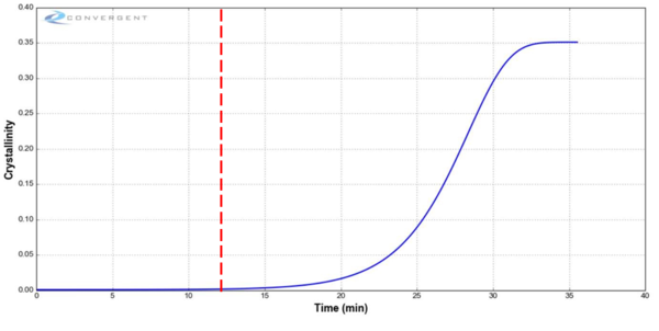
However, characterizing these materials is only the first step needed to solve this industrial problem. These process charts do not account for the physics of the manufacturing system, which is composed of various boundary conditions and other properties. For example, the thickness of the composite laminated used is critical, as the thicker the part, the greater the thermal mass and given the low thermal diffusivity of composites, the cooling rate is not only slowed, but a significant gradient is also developed through the thickness of the part. Software that uses the finite element (FE) method can model this type of system, incorporating size-scaling features, such as part thickness, making the problem more mathematically complex. Convergent Manufacturing Technologies (CMT) based in Vancouver B.C. is a company that specializes in this field and has produced a simulation package called RAVEN, tailored to composites. For example, setting up a simulation profile for a 1mm thick PEEK composite part, with an external boundary condition of temperature starting at 300°C and cooling at 10°C/min, yields the plot shown in the figure below. This plot represents the RC for the centre of this part. These boundary conditions, part configurations, material properties and other features, can be parametrically changed and recorded, to thoroughly and quickly explore the design space.
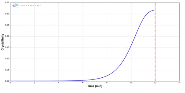
The curve reaches a plateau after approximately 35 minutes. The roll forming process may be designed, such that the final rolling action is applied at 12 minutes after cooling begins. This figure shows that at 12 minutes, the RC is close to zero, meaning that the RC will develop further well after all rolling has finished, which may result in a range of post-manufacture issues, such as residual stresses and deformation. The figure below shows the same RC profile for the PEEK material, but at a cooling rate of 30°C/min. It can be seen that at a time of 12 minutes, the plateau has been reached and the material is safer to consolidate at this time.
This type of approach is illustrative of a “right-sized” approach to manufacturing engineering, where simulation and other tools are used early on in the process to make critical decisions. In this example, the company has used right-sized simulation to help design their product to be manufacturable.
Outcome[edit | edit source]
It has been shown how the right-sized simulation approach can be used to better support decision making in the field of composites manufacturing engineering. This is an important part of building a complex and multi-physics system, which also aims to reduce risk.
Related pages[edit | edit source]
- Thermoplastic polymers
- Consolidation of Thermoplastics
- Pultrusion of Thermoplastic Composites
- Practice for developing a thermal transformation process step
Related pages
References
- ↑ [Ref] Strong, B.A. (2008). Fundamentals of composites manufacturing : materials, methods and applications. Society of Manufacturing Engineers, Dearborn, Mich., ©2008.CS1 maint: uses authors parameter (link) CS1 maint: date and year (link)
- ↑ [Ref] Lynam, C. (2011). Predicting thermoplastic deformations during roll forming of thermoplastic matrix composites (Thesis).CS1 maint: uses authors parameter (link)
- ↑ [Ref] Schuetze, D. (2013). A numerical model for predicting and optimising the termpature profile in multi-stage roll forming of thermoplastic composites (Thesis).CS1 maint: uses authors parameter (link)
| About | Help |
Welcome
Welcome to the CKN Knowledge in Practice Centre (KPC). The KPC is a resource for learning and applying scientific knowledge to the practice of composites manufacturing. As you navigate around the KPC, refer back to the information on this right-hand pane as a resource for understanding the intricacies of composites processing and why the KPC is laid out in the way that it is. The following video explains the KPC approach:
Understanding Composites Processing
The Knowledge in Practice Centre (KPC) is centered around a structured method of thinking about composite material manufacturing. From the top down, the heirarchy consists of:
- The factory
- Factory cells and/or the factory layout
- Process steps (embodied in the factory process flow) consisting of:
The way that the material, shape, tooling & consumables and equipment (abbreviated as MSTE) interact with each other during a process step is critical to the outcome of the manufacturing step, and ultimately critical to the quality of the finished part. The interactions between MSTE during a process step can be numerous and complex, but the Knowledge in Practice Centre aims to make you aware of these interactions, understand how one parameter affects another, and understand how to analyze the problem using a systems based approach. Using this approach, the factory can then be developed with a complete understanding and control of all interactions.
Interrelationship of Function, Shape, Material & Process
Design for manufacturing is critical to ensuring the producibility of a part. Trouble arises when it is considered too late or not at all in the design process. Conversely, process design (controlling the interactions between shape, material, tooling & consumables and equipment to achieve a desired outcome) must always consider the shape and material of the part. Ashby has developed and popularized the approach linking design (function) to the choice of material and shape, which influence the process selected and vice versa, as shown below:
Within the Knowledge in Practice Centre the same methodology is applied but the process is more fully defined by also explicitly calling out the equipment and tooling & consumables. Note that in common usage, a process which consists of many steps can be arbitrarily defined by just one step, e.g. "spray-up". Though convenient, this can be misleading.
Workflows
The KPC's Practice and Case Study volumes consist of three types of workflows:
- Development - Analyzing the interactions between MSTE in the process steps to make decisions on processing parameters and understanding how the process steps and factory cells fit within the factory.
- Troubleshooting - Guiding you to possible causes of processing issues affecting either cost, rate or quality and directing you to the most appropriate development workflow to improve the process
- Optimization - An expansion on the development workflows where a larger number of options are considered to achieve the best mixture of cost, rate & quality for your application.
To use this website, you must agree to our Terms and Conditions and Privacy Policy.
By clicking "I Accept" below, you confirm that you have read, understood, and accepted our Terms and Conditions and Privacy Policy.


