Developing for Future Production Scale Up - C113
| Developing for Future Production Scale Up | |||||||
|---|---|---|---|---|---|---|---|
| Case study | |||||||

| |||||||
| Document Type | Case study | ||||||
| Document Identifier | 113 | ||||||
| Tags | |||||||
| Objective functions |
| ||||||
| MSTE workflow | Development | ||||||
| Prerequisites | |||||||
Summary[edit | edit source]
A ground transportation OEM redesigned a composite external door panel for one of their vehicles and required a small number of units to be produced for prototyping and testing purposes. Prototype and test components were produced using an open-mold hand-layup process. After the testing was completed, the manufacturing process was switched to Light RTM (LRTM) to meet production rate requirements. During the hand-layup prototyping phase the tooling was designed to be re-used as the A-side tool for the higher-rate LRTM process. This allowed for design changes to be identified prior to producing the B-side tooling and reduced overall tooling costs to move from hand-layup to LRTM. See A184
Challenge[edit | edit source]
The LRTM process is commonly used to produce composite components in low-to-mid volume ground transportation (transit and rail) applications. The geometry for the A-side is generally defined around aesthetic and functional requirements while the B-side tooling geometry accounts for interfaces, core geometry and laminate thickness. If modifications are required to the part construction after initial prototyping and testing, the B-side geometry is likely to change which requires a new B-side tool to be designed and produced for LRTM manufacturing.
Approach[edit | edit source]
Requirements for the external door panel included:
- Maximum allowable weight to keep overall vehicle weight low for fuel efficiency.
- Maximum deflection value when the door is in a closed position.
- Minimum strength value to ensure the door does not break when opened and closed.
- Interface locations to meet up with other body panels and to ensure the door latching mechanism works correctly.
- Class A surface finish.
The structure was designed to be produced using the LRTM process utilizing a semi-rigid glass fibre B-side cover and polypropylene flow-media integrated into the laminate. This process was used for similar components on the vehicle and provided a cost-effective manufacturing method that could meet all of the design requirements listed above.
A small number of units were required for initial prototyping and testing to validate the structure and determine if any changes were required prior to moving into full production. The LRTM process can accommodate small changes in laminate construction within the part cavity but frequently require replacement of the B-side tooling if the part cavity needs to be modified. This can be costly as the B-side tool typically costs about twice as much as the A-side tool. To reduce the up-front tooling cost, the prototype components were produced using open-mold hand-layup which did not require a B-side tool. The prototype tooling was built from glass fibre with a backing structure added for strength. It was designed to be re-used as the A-side tool for full-scale production to reduce overall tooling costs.
To produce prototype and initial units using an open-mold/Wet layup process, material substitutions were made to approximate the part performance as closely as possible. The laminate construction for the LRTM version of the structure consisted of both randomly oriented and directional glass fibre plies, foam core (see Cores & inserts), and a polypropylene flow media layer. In addition, a series of metallic plates were laminated into the structure at attachment points.
The polypropylene layer used is designed to work with a closed molding process with a rigid or semi-rigid B-side tool within a given compaction range. It is not suitable for use in open-mold processing. This is because it requires vacuum to pull the resin through the polypropylene layer and does not wet out sufficiently using wet layup processing. The overall stiffness of the structure was primarily obtained through the core geometry as bending stiffness was critical. It was determined by calculating the bending stiffness (see Macro-Mechanics) that replacing the polypropylene flow media with additional chopped strand mat to match the designed laminate thickness would have minimal impact on the structural performance of the door. This would not always be the case, depending on overall configuration of the structure and loading situations, and needs to be evaluated on a case-by-case basis. For example, replacing the polypropylene flow media with chopped strand mat increases the tensile stiffness of the component. This substitution would not be appropriate if the performance of the part under tension loads was critical.
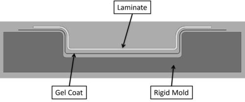
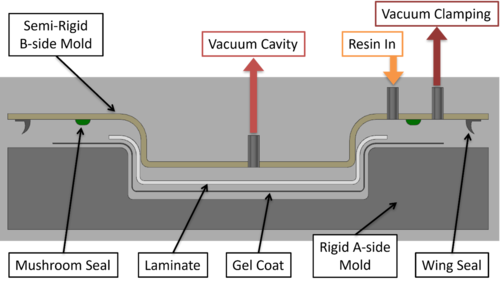
For this structure, the manufacturing process for full-scale production was selected to be LRTM prior to producing tooling for the hand-layup components. The A-side geometry of the component was not anticipated to change between prototype and production designs. It was decided that to eliminate the need to produce both new A-side and B-side tooling after prototyping, the open-mold layup tooling would be designed and produced with a wider flange that could accommodate the vacuum channel and seals required for use in the LRTM process. Examples showing typical open-mold and LRTM tooling is shown in Figs. 1 and 2. Adjusting the prototype tooling for future LRTM manufacturing required a marginal cost increase to the prototype tooling, but reduced overall tooling costs of the program.
Prototype units were produced using hand-layup tooling, then tested. The testing included fit-up testing, opening and closing load cycling, and in-service driving tests. After testing, design changes to the core and metal interface plates were implemented for better fit-up with the vehicle structure. This resulted in changes to the part cavity design for the LRTM version. These changes were implemented prior to producing the B-side cover for full-scale production.
Outcome[edit | edit source]
Design of the new door was tested using representative units produced using an open-mold hand-layup process before being transitioned to a LRTM manufacturing process for full-scale production. Performing evaluation on hand-layup units rather than ones produced using LRTM allowed for testing without the initial up fron cost for a B-side tool, which typically accounts for 2/3 of the tooling costs. The test results allowed for design changes of the part cavity to be identified and implemented prior to fabrication of the B-side cover for production. The tooling used for hand-layup prototypes was designed with a larger flange so that it could be re-used as the A-side tool for the LRTM process. This resulted in a cost reduction of approximately 25% to move from the hand-layup tooling to LRTM.
For more information see Practice for troubleshooting a Light RTM step and A184
Related pages[edit | edit source]
- Light resin transfer moulding (Light RTM)
- Vacuum assisted resin transfer moulding (VARTM)
- Practice for Identifying Process Steps
- Process selection for production scale-up
- Practice for troubleshooting a Light RTM step
- Resin Behaviour During Processing: What are the key resin properties to consider when developing a manufacturing process?
Related pages
| About | Help |
Welcome
Welcome to the CKN Knowledge in Practice Centre (KPC). The KPC is a resource for learning and applying scientific knowledge to the practice of composites manufacturing. As you navigate around the KPC, refer back to the information on this right-hand pane as a resource for understanding the intricacies of composites processing and why the KPC is laid out in the way that it is. The following video explains the KPC approach:
Understanding Composites Processing
The Knowledge in Practice Centre (KPC) is centered around a structured method of thinking about composite material manufacturing. From the top down, the heirarchy consists of:
- The factory
- Factory cells and/or the factory layout
- Process steps (embodied in the factory process flow) consisting of:
The way that the material, shape, tooling & consumables and equipment (abbreviated as MSTE) interact with each other during a process step is critical to the outcome of the manufacturing step, and ultimately critical to the quality of the finished part. The interactions between MSTE during a process step can be numerous and complex, but the Knowledge in Practice Centre aims to make you aware of these interactions, understand how one parameter affects another, and understand how to analyze the problem using a systems based approach. Using this approach, the factory can then be developed with a complete understanding and control of all interactions.
Interrelationship of Function, Shape, Material & Process
Design for manufacturing is critical to ensuring the producibility of a part. Trouble arises when it is considered too late or not at all in the design process. Conversely, process design (controlling the interactions between shape, material, tooling & consumables and equipment to achieve a desired outcome) must always consider the shape and material of the part. Ashby has developed and popularized the approach linking design (function) to the choice of material and shape, which influence the process selected and vice versa, as shown below:
Within the Knowledge in Practice Centre the same methodology is applied but the process is more fully defined by also explicitly calling out the equipment and tooling & consumables. Note that in common usage, a process which consists of many steps can be arbitrarily defined by just one step, e.g. "spray-up". Though convenient, this can be misleading.
Workflows
The KPC's Practice and Case Study volumes consist of three types of workflows:
- Development - Analyzing the interactions between MSTE in the process steps to make decisions on processing parameters and understanding how the process steps and factory cells fit within the factory.
- Troubleshooting - Guiding you to possible causes of processing issues affecting either cost, rate or quality and directing you to the most appropriate development workflow to improve the process
- Optimization - An expansion on the development workflows where a larger number of options are considered to achieve the best mixture of cost, rate & quality for your application.
To use this website, you must agree to our Terms and Conditions and Privacy Policy.
By clicking "I Accept" below, you confirm that you have read, understood, and accepted our Terms and Conditions and Privacy Policy.


