Reinforcement properties - A213
| Reinforcement properties | |
|---|---|
| Foundational knowledge article | |

| |
| Document Type | Article |
| Document Identifier | 213 |
| Themes | |
| Tags | |
Overview[edit | edit source]
This page provides links to composite reinforcement properties. In the Knowledge in Practice Centre (KPC), reinforcement properties are defined as properties that describe the composite reinforcement material.
The role of the reinforcement is primarily to be the load bearing constituent in the composite material by providing strength and stiffness. Reinforcement may also provide other secondary and unique properties such as: heat and electricity conduction (in the case of carbon), thermal and electrical insulation (in the case of glass), abrasion resistance (in the case of aramid).
Below are the reinforcement property pages found in the KPC:
Chemical Properties[edit | edit source]
Coming soon.
- Surface reactivity (effect of sizing)
- Degradation
Physical Properties[edit | edit source]
Fibre volume fraction[edit | edit source]
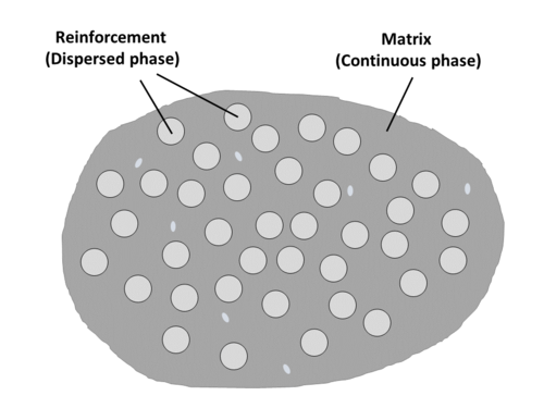
Fibre volume fraction (\(V_f\)) describes the volume fraction of fibres in the composite with respect to total composite volume (matrix + fibre + voids).
It is cacluated as follows\[V_f = \frac{v_f}{v} = 1 - V_m - V_v\]
Where,
\(v_f = \) Volume of fibres
\(v = \) Total composite volume (volume matrix + volume fibres + volume voids)
\(V_m = \) Volume fraction matrix
\(V_v = \) Volume fraction voids
The mechanical properties of a composite material increase with greater proportions of fibre reinforcement content (greater value of \(V_f\)).
Material datasheets often report the composite constituent amounts in weight percent instead of volume percent, and care must be taken to avoid confusion between volume and weight percentages. Conversion between weight and volume can be made if both matrix density and fibre density are known using the density - weight/volume relationships.
\(\rho_f = \frac{w_f}{v_f}\)
\(\rho_m = \frac{w_m}{v_m}\)
\(\rho_c = \frac{{w_f}+{w_m}}{{v_f}+{v_m}+{v_v}} = \frac{{\rho_f v_f}+{\rho_m v_m}}{v}\)
Where,
\(\rho_f = \) Fibre density
\(\rho_m = \) Matrix density
\(\rho_c = \) Composite density
\(w_f = \) Weight of fibres
\(w_m = \) Weight of matrix
\(v_m = \) Volume of matrix
\(v_v = \) Volume of voids
KPC page for fibre volume fraction coming soon.
Fibre weight fraction[edit | edit source]
For the purpose of fabrication, it is natural to describe the constituents of a composite in terms of their proportions by weight. Constituents (fibre, matrix, fillers, etc.) are weighed before processing, and laminate weight per unit area may be a design specification.
Fibre weight fraction (\(W_f\)) describes the weight fraction of fibres with respect to the total composite weight (total weight of the composite = weight of fibers + weight of matrix)
The term weight fraction may be applied to any of the constituents. Similarly, resin weight fraction, filler weight fraction, etc.
Fibre weight fraction is calculated as follows\[W_f = \frac{w_f}{w}\]
Similarly, weight fraction matrix (\(W_m\))\[W_f = \frac{w_m}{w}\]
Where,
\(w_f = \) Weight of fibres
\(w_m = \) Weight of matrix
\(w = \) Total composite weight (weight fibres + weight matrix)
With the total weight of the composite\[w = w_f + w_m = 1 = \frac{w_f}{w} = \frac{w_m}{w}\]
As mentioned for fibre volume fraction, material datasheets often report constituent amounts in weight percent instead of volume percent, and confusion between volume and weight percentages should not be made. While care must be taken not to inadvertently interchange the two, conversions between weight and volume can be made if both matrix density and fibre density are known.
\(\rho_f = \frac{w_f}{v_f}\)
\(\rho_m = \frac{w_m}{v_m}\)
\(\rho_c = \frac{{w_f}+{w_m}}{{v_f}+{v_m}+{v_v}} = \frac{{\rho_f v_f}+{\rho_m v_m}}{v}\)
Where,
\(\rho_f = \) Fibre density
\(\rho_m = \) Matrix density
\(\rho_c = \) Composite density
\(v_f = \) Volume of fibres
\(v_m = \) Volume of matrix
\(v_v = \) Volume of voids
\(v = \) Total volume of composite
KPC page for fibre weight fraction coming soon.
Fibre diameter[edit | edit source]
The small diameter combined with long length aspect ratio of fibrous reinforcement is an important reinforcement property cosideration for several reasons:
- Small fibre diameter reduces the probability of imperfections (see yield and fracture to learn more about this effect.)
- A high aspect ratio (fibre diameter to length) to effectively transfer the applied load to the load-bearing reinforcement
- Increases flexibility to aid in processing
The following are typical fibre sizes of popular fibre reinforcements:
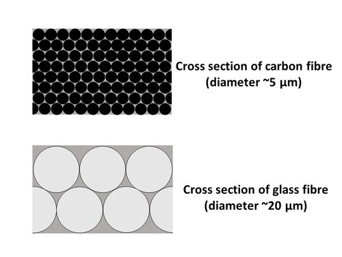
- Carbon: ~5 μm diameter
- Glass: ~20 μm diameter
- Kevlar 49: ~12 μm diameter
When considering packing factors, approximately 6 glass fibres fill the space of roughly 92 carbon fibres.
KPC page for fibre diameter coming soon.
Fibre tow size[edit | edit source]
A tow is a bundle or yarn of individual fibres that are then woven together into reinforcement textiles. Typically, smaller tows are better because they result in a more homogeneous material.
However, the larger the tow:
- The faster it is to deposit the fibre material
- The easier is it for resin to flow in the gaps inbetween the fibre tows
- The harder it is for resin to saturate within the fibre tows between the individual fibres
Typical tow sizes found for composite fibre reinforcements:
- 1k (thousand)
- 3k
- 6k
- 12k
- 24k
- 50k
KPC page for fibre tow size coming soon.
Fibre areal weight[edit | edit source]
Areal weight (or fiber areal weight, AW ) refers to the mass/weight of fiber per unit area. (Typically in g/m2 gsm ) or ounces/yard2 (often just called ounces). Areal weight depends on tow size and fiber architecture (weaving, density, etc.).
Fibre areal weight can be applied in the determination of reinforcement content (\(V_r\) or \(V_f\) for fibres) of a composite\[V_r=\frac{AW_r \times N}{\rho_r \times h}\]
where,
\(AW_r = \) Reinforcement areal weight per layer/ply [kg/m2]
\(N = \) Number of reinforcement layers/plies
\(\rho_r = \) Reinforcement (e.g. fibre, \(\rho_f\)) density [kg/m3]
\(h = \) Composite thickness [m]
KPC page for fibre areal weight coming soon.
Fibre preform permeability[edit | edit source]
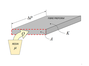
Permeability refers to the ease of flow through a porous material, in this case the resin flow through the interconnected porous space in the fibre preform. For resin infusion processes (e.g. RTM), the permeability of the fibre preform is an important property as liquid resin is infused into the fibre reinforcement preform.
Darcy’s law governs flow through porous medium\[Q = -\frac{KA}{\mu}\frac{\Delta P}{x}\]
Where,
\(Q = \) Volumetric flow rate
\(K = \) Preform permeability
\(A = \) Preform cross-sectional area
\(\mu = \) Resin viscosity
\(\Delta P = \) Pressure differential across preform
\(x = \) In-plane flow distance of pressure differential
KPC page for fibre preform permeability coming soon.
Physical properties coming soon[edit | edit source]
- Density
- Suface area
Mechanical Properties[edit | edit source]
Yield and fracture[edit | edit source]
The yield and fracture behaviour of reinforcement is heavily influenced by the geometry and size form of the reinforcement material. For example, reinforcement materials are often employed in a thin fibre form that results in enhanced high strength. Glass and carbon fibre reinforcement are notable examples of this.
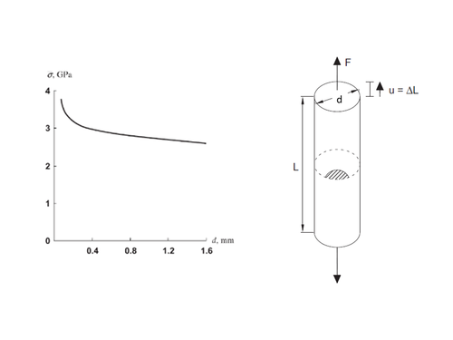
For most materials, and especially pronounced for brittle materials, a small diameter fibre is much stronger than the bulk form of the same material. The reasoning, as fibre diameter decreases, the probability of critical flaws that lead to fracture and failure in the material diminishes [1].
The critical stress \(\sigma\) for failure depends on the absolute value of crack length or size of the imperfection. The thinner the wire, the smaller the size of imperfection that can exist in the fiber. Therefore, the smaller the fiber, the higher the critical stress that can be supported by the material.
This phenomenon that sees a reduction in critical flaws allows for the use of typically brittle materials, such as glass and carbon, to be used as high tensile strength composite reinforcement when in a small diameter fibre form is used.
KPC page for reinforcement yield and fracture coming soon.
Mechanical properties coming soon[edit | edit source]
- Textile mechanics
Property Measurement[edit | edit source]
For methods to obtain material property values, please see the Foundational Methods Documents page:
Link to Foundational Method Documents page
Other Material Properties[edit | edit source]
Related pages
References
| About | Help |
Welcome
Welcome to the CKN Knowledge in Practice Centre (KPC). The KPC is a resource for learning and applying scientific knowledge to the practice of composites manufacturing. As you navigate around the KPC, refer back to the information on this right-hand pane as a resource for understanding the intricacies of composites processing and why the KPC is laid out in the way that it is. The following video explains the KPC approach:
Understanding Composites Processing
The Knowledge in Practice Centre (KPC) is centered around a structured method of thinking about composite material manufacturing. From the top down, the heirarchy consists of:
- The factory
- Factory cells and/or the factory layout
- Process steps (embodied in the factory process flow) consisting of:
The way that the material, shape, tooling & consumables and equipment (abbreviated as MSTE) interact with each other during a process step is critical to the outcome of the manufacturing step, and ultimately critical to the quality of the finished part. The interactions between MSTE during a process step can be numerous and complex, but the Knowledge in Practice Centre aims to make you aware of these interactions, understand how one parameter affects another, and understand how to analyze the problem using a systems based approach. Using this approach, the factory can then be developed with a complete understanding and control of all interactions.
Interrelationship of Function, Shape, Material & Process
Design for manufacturing is critical to ensuring the producibility of a part. Trouble arises when it is considered too late or not at all in the design process. Conversely, process design (controlling the interactions between shape, material, tooling & consumables and equipment to achieve a desired outcome) must always consider the shape and material of the part. Ashby has developed and popularized the approach linking design (function) to the choice of material and shape, which influence the process selected and vice versa, as shown below:
Within the Knowledge in Practice Centre the same methodology is applied but the process is more fully defined by also explicitly calling out the equipment and tooling & consumables. Note that in common usage, a process which consists of many steps can be arbitrarily defined by just one step, e.g. "spray-up". Though convenient, this can be misleading.
Workflows
The KPC's Practice and Case Study volumes consist of three types of workflows:
- Development - Analyzing the interactions between MSTE in the process steps to make decisions on processing parameters and understanding how the process steps and factory cells fit within the factory.
- Troubleshooting - Guiding you to possible causes of processing issues affecting either cost, rate or quality and directing you to the most appropriate development workflow to improve the process
- Optimization - An expansion on the development workflows where a larger number of options are considered to achieve the best mixture of cost, rate & quality for your application.
To use this website, you must agree to our Terms and Conditions and Privacy Policy.
By clicking "I Accept" below, you confirm that you have read, understood, and accepted our Terms and Conditions and Privacy Policy.


