Heat transfer - A132
| Heat transfer | |
|---|---|
| Foundational knowledge article | |
| |
| Document Type | Article |
| Document Identifier | 132 |
| Themes | |
| Relevant Class |
Material |
| Tags | |
| Prerequisites | |
Introduction[edit | edit source]
Heat transfer is the physics process responsible for the redistribution of thermal heat energy between systems. For composites, this includes the redistribution of heat both within the laminate itself, and between the laminate body and its surrounding environment. The heat transfer process has important roles in both the composite manufacturing process and the operational service of the composite material.
Scope[edit | edit source]
This page introduces the fundamental topic of heat transfer and its application to composites processing. It describes the three main mechanisms of heat transfer, i.e. thermal conduction, thermal convection and thermal radiation, outlines the energy equation, measurement techniques, and the modelling of heat transfer in process simulation.
Significance[edit | edit source]
Heat transfer is a fundamental component of the composite manufacturing process. In many cases, sufficient amounts of heat must be imposed on the laminate during the manufacturing process for its physical, and in certain cases chemical transformation into the final composite part.
Precise control of the temperature imposed on the laminate during manufacturing plays an important role in the following aspects:
- Thermoset matrix: ensuring a suitable level of cure is achieved for the intended mechanical properties. At the same time, tight control of temperature is critical during processing to control the evolution of cure and mitigate the development of defects due too little or too much resin flow
- Thermoplastic matrix: ensuring sufficient heating for melting and flow, and cooling for recrystallization
- All matrix types: influencing the microstructure distribution of the reinforcement fibres and matrix tougheners, morphology of matrix tougheners, final matrix porosity
Prerequisites[edit | edit source]
Recommended documents to review before, or in parallel with this document:
Overview[edit | edit source]
Heat Transfer Mechanisms[edit | edit source]
Fundamentally, heat transfer is organized into three main mechanisms:
- Conduction
- Convection
- Radiation (considered negligible in a majority of composites processing scenarios)
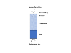
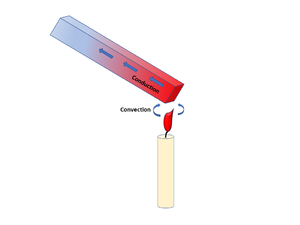
For a system, heat transport can involve multiple mechanisms. Using the classic example of a metal rod being heated over a flame; the heat being transferred from the flame to the rod is considered to be by convection, while the heat transferred along the rod itself is by conduction [1]. Applying this analogy to the composites processing scenario for a laminate curing in an oven or autoclave environment; the hot air transfers heat by convection, while the heat transfer between the tool and laminate part, and within the laminate itself is then by conduction.
Conduction[edit | edit source]
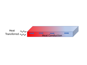
Conduction is a heat transfer mode associated with the microscopic collisions between high energy particles and adjacent lower energy particles causing a redistribution of the kinetic energy within a material or medium. The heat flow is proportional to the temperature gradient imposed and the intrinsic properties of the material. Conduction is considered the primary heat transfer mechanism in solid materials.
Convection[edit | edit source]
Convection is a heat transfer mode driven by the bulk motion of a fluid. Energy transport by convection (e.g. heat) results from the combination of two heat transfer mechanisms: conduction and the fluid flow process of advection. Convection takes place in the presence of fluid motion and can occur by forced fluid motion (forced convection) or by natural fluid motion (natural convection). In composites processing, convection is an important heat transfer mechanism occurring in oven and autoclave processing methods.
There are two types of convection transport: forced convection and free convection. These two modes of convection differ by the driving force leading the fluid flow:
Forced Convection[edit | edit source]
In forced convection, the motion of the fluid is governed by external mechanical forces and typically controlled in production by a pump or a fan. For heating equipment like autoclaves or ovens, flowing gas driven by a fan is used to heat the part-tool assembly.
Natural Convection[edit | edit source]
In free convection, also known as natural convection, the motion of the fluid is driven by the temperature gradients in the fluid without external input. This occurs for open-air processes without a fan, where air movement may develop due to temperature-induced buoyant forces acting on the air. Similarly, a hot part naturally cooling in an open air environment is an example of natural convection heat transfer taking place.
Radiation[edit | edit source]
In composites processing, conduction and convection are the dominant heat transfer mechanisms and thermal radiation is generally negligible [2][3].
Heat Transfer Interactions During Composites Processing[edit | edit source]
Link to main System Interactions page
Heat plays a critical role in the composites manufacturing process, controlling resin flow, cure and crystallization kinetics, and even the physical distribution and morphology of the various laminate constituents. During processing, heat is transferred between the laminate, tooling and manufacturing equipment. Heat transfer in composites processing is a systems problem, where the laminate part, tool, and heating equipment all interact together. During heated manufacturing processes, thermal heat is transferred from the manufacturing equipment to the laminate to form the final part. For thermoset matrix composites (e.g. polyester, epoxy) the heat is required for the curing of the thermoset resin, while for thermoplastic matrix composites the heat is required for melting (flow) and recrystallization (solidification) of the matrix.
Example of Thermal Process Interactions[edit | edit source]
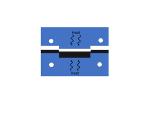
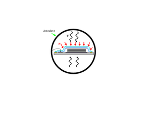
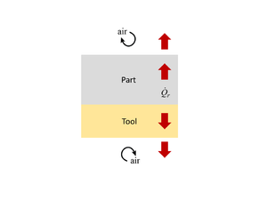
Two typical processing examples illustrating the role of heat transfer in the composite manufacturing process are given below (for further details of the interactions outlined, please see the Systems Interactions page):
| Manufacturing Process | Heat Transfers Involved | |
|---|---|---|
Hot Press[edit | edit source] |
| |
Autoclave and Convection Oven[edit | edit source] |
|
System Heat Sources and Heat Sinks[edit | edit source]
Like water flowing downstream, thermal heat flows from regions of high thermal energy (warmer temperature) to regions of lower thermal energy (cooler temperature). Whether a laminate heats up or cools down depends on the temperature gradient present between the laminate and the surrounding system. The thermal heat energy flowing into or out of the laminate can be described by considering the potential heat sources (heat input) and heat sinks (heat removal) in the system.
Heat Sources (adds heat)[edit | edit source]
- Equipment with a heat source
- Tool when hot
- Material when generating heat (i.e. exothermic curing reaction of a thermoset resin)
Heat Sinks (removes heat)[edit | edit source]
- Equipment with a cooling system
- Tool when cold
- Material when absorbing heat (i.e. melting of a thermoplastic resin)
All system objects can act as either a heat source or a heat sink. Whether an object is a source or a sink is dependent upon the object's temperature in comparison to other surrounding objects in its environment.
Modelling[edit | edit source]
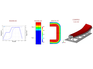
Heat transfer can be modelled to various levels of complexity, from 0-D (no part thickness or dimensional considerations) up through 3-D.
The necessary number of dimensions to obtain sufficient accuracy is dependent on the geometry of the part, and the analysis being performed. For some cases, 1-D modelling is sufficient, while in other cases 2-D and 3-D modelling may be required.
In many cases, the typical laminate part aspect ratio (thickness is order of magnitudes less in comparison to length and depth dimensions) and part geometry generally allows for simple 1-D modelling of the through-thickness thermal distribution to often be sufficient.
The Energy Equation[edit | edit source]
The heating of a laminate can be simplified and described as a heat energy balance, where\[Rate\ of\ heat\ increase = Rate\ of\ heat\ addition\ by\ conduction\]
Modelled, this can be presented as the following general heat balance equation\[\frac{\partial}{\partial t}(\rho c_pT)= \frac{\partial}{\partial x}\Bigl(k_{xx}\frac{\partial T}{\partial x}\Bigr)+\frac{\partial}{\partial y}\Bigl(k_{yy}\frac{\partial T}{\partial y}\Bigr)+\frac{\partial}{\partial z}\Bigl(k_{zz}\frac{\partial T}{\partial z}\Bigr)\]
Breaking down the general heat balance equation by the individual heat components,
\(\frac{\partial}{\partial t}(\rho c_pT)=\) Heat accumulation in the laminate
\(\frac{\partial}{\partial x}\Bigl(k_{xx}\frac{\partial T}{\partial x}\Bigr)+ ... =\) Conduction heat transfer contributions
Where,
\(t =\) Time [s]
\(\rho =\) Density [kg/m3]
\(c_p =\) Specific heat capacity [J/kg·K]
\(T =\) Temperature [K]
\(k =\) Thermal conductivity (in principle direction x, y, or z) [W/m·K]
\(x,\, y,\, z =\) Respective principle direction x, y, or z
The rate of heat transferred into the system is provided by the heating equipment or environment (room temperature cure). If this heat transfer boundary condition is convective in nature (moving air), the heating rate can be described by\[\dot Q = hA\Delta T\]
Where,
\( h =\) Convective heat transfer coefficient [W/m2·K]
\(A = \) Surface area [m2]
\(\Delta T = \) Change in temperature [K]
During the curing cycle for thermosets, internal heat is generated by the exothermic cross-linking reaction. In this scenario, the heat balance equation gains an additional \(\dot Q_r\) term (reaction heating rate)\[\frac{\partial}{\partial t}(\rho c_pT)= \frac{\partial}{\partial x}\Bigl(k_{xx}\frac{\partial T}{\partial x}\Bigr)+\frac{\partial}{\partial y}\Bigl(k_{yy}\frac{\partial T}{\partial y}\Bigr)+\frac{\partial}{\partial z}\Bigl(k_{zz}\frac{\partial T}{\partial z}\Bigr)+\dot Q_r\]
The internal heat generation modelled as\[\dot Q_r = \frac{d\ x}{dt}(1-V_f)\rho_r H_R\]
Where,
\(\frac{d\ x}{dt} = \) Rate change of degree of cure [1/s]
\(V_f = \) Volume fraction fibre
\(\rho_r = \) Density of resin [kg/m3]
\(H_R = \) Total heat of reaction [J/kg]
1-D Thermal Modelling Example[edit | edit source]
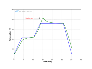
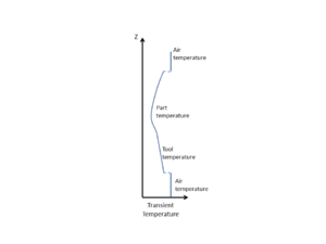
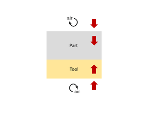
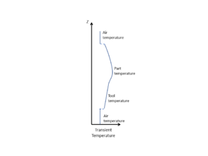
For many cases, 1-D modelling of the through-thickness thermal distribution is sufficient. Provided here is an example for the curing of a thermoset matrix laminate modelled 1-D in the through-thickness direction. Shown are the heat transfer interactions, temperature profile, and heat equation involved for the lay-up stack for the heating stage, and after the thermoset exothermic reaction has kicked off with internal generated heat being released. If a substantial amount of heat is generated, the heat may leave the laminate and transfer into its surrounding environment.
Example: Autoclave cured carbon fibre/epoxy prepreg laminate[edit | edit source]
- Scenario Setup:
| Laminate | 1-D (through-thickness) Lay-up Stack | Temperature History |
|---|---|---|
- 1-D Thermal Modelling Representation:
| Temperature Profile | Heat Transfer System Interactions | Heat Equations | |
|---|---|---|---|
Laminate Heat Up[edit | edit source] |
Heat Transfer Balance:
Rate of heat transfer by convection\[\dot Q = hA\Delta T\]
Laminate and tool energy balance\[\frac{\partial}{\partial t}(\rho c_pT)= \frac{\partial}{\partial z}\Bigl(k_{zz}\frac{\partial T}{\partial z}\Bigr)\]
Rate of heat transfer by convection\[\dot Q = hA\Delta T\] | ||
Laminate Exotherm[edit | edit source] |
Heat Transfer Balance:
Rate of heat transfer by convection\[\dot Q = hA\Delta T\]
Laminate energy balance\[\frac{\partial}{\partial t}(\rho c_pT)= \frac{\partial}{\partial z}\Bigl(k_{zz}\frac{\partial T}{\partial z}\Bigr)+\dot Q_r\]
Rate of heat transfer by convection\[\dot Q = hA\Delta T\] |
Measurement[edit | edit source]
The heat transfer process can be measured by proxy in two ways:
- Temperature measurement: tracking temperature evolution (with time and position) to develop an understanding of the thermal management system and when available to validate a thermal model
- Heat transfer coefficients: measuring the heat transfer coefficients, conduction \(k\) and convection \(h\) to use them for thermal modelling as inputs
Listed below are the different techniques to measure temperature and heat transfer coefficients.
Temperature Measurement[edit | edit source]
- Thermocouple
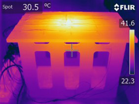
- Infrared Camera
- Fibre Optic
Heat Transfer Coefficients[edit | edit source]
Thermal Conductivity[edit | edit source]
Convective Heat Transfer Coefficient[edit | edit source]
- The following table from Slesinger et al. [4], provides a list of the possible methods available to measure airflow and convective heat transfer coefficients (HTC).
Airflow and heat transfer measurement methods. Source: [4][edit | edit source]
| Advantages | Disadvantages | |
|---|---|---|
| Anemometers | • Measures actual velocity values
|
• Non-directional
• Noisy results (turbulence) • Expensive, difficult to position • Local – need to know where |
| Calorimeters | • Inexpensive
• Provides representative HTC values |
• Time consuming data reduction
• Non-directional • Length scale dependency (real HTC may be different) • Local - need to know where |
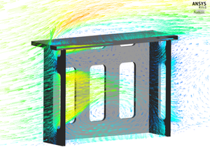
| CFD | • Shows velocity magnitude and direction
• All areas can be evaluated • Parametric evaluation |
• Model may lack realistic detail
• Time consuming, expensive • Requires skilled personnel • Must be validated experimentally |
| Instrumented Part | • Provides actual HTC | • Accuracy limited by number of thermocouples
• Time consuming data reduction •Autoclave load or part geometry changes require new test • Non-directional • Local - need to know where |
| Video | • Inexpensive
• Intuitive to analyze • Large areas can easily be monitored |
• Qualitative
• Limited to ambient temperature and pressure |
Explore this area further
Related pages
| Page type | Links |
|---|---|
| Introduction to Composites Articles | |
| Foundational Knowledge Articles | |
| Foundational Knowledge Method Documents | |
| Foundational Knowledge Worked Examples | |
| Systems Knowledge Articles | |
| Systems Knowledge Method Documents | |
| Systems Knowledge Worked Examples | |
| Systems Catalogue Articles | |
| Systems Catalogue Objects – Material | |
| Systems Catalogue Objects – Shape | |
| Systems Catalogue Objects – Tooling and consumables | |
| Systems Catalogue Objects – Equipment | |
| Practice Documents | |
| Case Studies | |
| Perspectives Articles |
|
References
- ↑ [Ref] Gaskell, David R. (1992). An Introduction to Transport Phenomena in Materials Engineering. Macmillan Publishing Company. ISBN 0023407204.CS1 maint: uses authors parameter (link) CS1 maint: date and year (link)
- ↑ [Ref] Slesinger, Nathan Avery (2010). Thermal Modeling Validation Techniques for Thermoset Polymer Matrix Composites (Thesis). doi:10.14288/1.0071063.CS1 maint: uses authors parameter (link)
- ↑ [Ref] Salagnac, P et al. (2004). "Curing of composites by radiation and natural convection in an autoclave". 50 (12). John Wiley & Sons, Ltd. doi:10.1002/aic.10224. ISSN 0001-1541. Cite journal requires
|journal=(help)CS1 maint: extra punctuation (link) CS1 maint: uses authors parameter (link) - ↑ 4.0 4.1 [Ref] Slesinger, Nathan et al. (2010). Simple Visualization of Autoclave Airflow Using Wireless Cameras. Society for the Advancement of Material and Process Engineering.CS1 maint: extra punctuation (link) CS1 maint: uses authors parameter (link) CS1 maint: date and year (link)
| About | Help |
Welcome
Welcome to the CKN Knowledge in Practice Centre (KPC). The KPC is a resource for learning and applying scientific knowledge to the practice of composites manufacturing. As you navigate around the KPC, refer back to the information on this right-hand pane as a resource for understanding the intricacies of composites processing and why the KPC is laid out in the way that it is. The following video explains the KPC approach:
Understanding Composites Processing
The Knowledge in Practice Centre (KPC) is centered around a structured method of thinking about composite material manufacturing. From the top down, the heirarchy consists of:
- The factory
- Factory cells and/or the factory layout
- Process steps (embodied in the factory process flow) consisting of:
The way that the material, shape, tooling & consumables and equipment (abbreviated as MSTE) interact with each other during a process step is critical to the outcome of the manufacturing step, and ultimately critical to the quality of the finished part. The interactions between MSTE during a process step can be numerous and complex, but the Knowledge in Practice Centre aims to make you aware of these interactions, understand how one parameter affects another, and understand how to analyze the problem using a systems based approach. Using this approach, the factory can then be developed with a complete understanding and control of all interactions.
Interrelationship of Function, Shape, Material & Process
Design for manufacturing is critical to ensuring the producibility of a part. Trouble arises when it is considered too late or not at all in the design process. Conversely, process design (controlling the interactions between shape, material, tooling & consumables and equipment to achieve a desired outcome) must always consider the shape and material of the part. Ashby has developed and popularized the approach linking design (function) to the choice of material and shape, which influence the process selected and vice versa, as shown below:
Within the Knowledge in Practice Centre the same methodology is applied but the process is more fully defined by also explicitly calling out the equipment and tooling & consumables. Note that in common usage, a process which consists of many steps can be arbitrarily defined by just one step, e.g. "spray-up". Though convenient, this can be misleading.
Workflows
The KPC's Practice and Case Study volumes consist of three types of workflows:
- Development - Analyzing the interactions between MSTE in the process steps to make decisions on processing parameters and understanding how the process steps and factory cells fit within the factory.
- Troubleshooting - Guiding you to possible causes of processing issues affecting either cost, rate or quality and directing you to the most appropriate development workflow to improve the process
- Optimization - An expansion on the development workflows where a larger number of options are considered to achieve the best mixture of cost, rate & quality for your application.
To use this website, you must agree to our Terms and Conditions and Privacy Policy.
By clicking "I Accept" below, you confirm that you have read, understood, and accepted our Terms and Conditions and Privacy Policy.

