Conduction - A118
| Conduction | |
|---|---|
| Foundational knowledge article | |

| |
| Document Type | Article |
| Document Identifier | 118 |
| Themes | |
| Relevant Class |
Material |
| Tags | |
| Prerequisites | |
Introduction[edit | edit source]
Conduction is a molecular heat transfer mode associated with the microscopic collisions between high energy particles and adjacent lower energy particles causing a redistribution of kinetic energy. Therefore, heat transfer by conduction occurs from regions of higher temperature to regions of lower temperatures.
Scope[edit | edit source]
This page explains thermal conduction in the context of composites processing and how it differs from other heat transfer mechanisms such as convection. Specifics about the material properties involved in thermal conduction are given in separate pages.
Significance[edit | edit source]
Conduction is the primary heat transfer mechanism in solid materials. It plays a critical role in composite manufacturing processes, responsible for heat flow in hot press forming platens, tooling and part through-thickness temperature gradients. Both steady-state and transient (non steady-state) conduction are introduced and discussed.
Prerequisites[edit | edit source]
Recommended documents to review before, or in parallel with this document:
Conduction overview[edit | edit source]
Conduction is a molecular heat transfer mode associated with the microscopic collisions between high energy particles and adjacent lower energy particles causing a redistribution of kinetic energy. Therefore, heat transfer by conduction occurs from regions of higher temperature to regions of lower temperatures. It is one of the are three main mechanisms of heat transfer.
Using the classic example of a metal rod being heated over a flame; the heat being transferred from the flame to the rod is considered to be by convection, while the heat transferred along the rod itself is by conduction [1]. Applying this analogy to the composites processing scenario for a laminate curing in an oven or autoclave environment; the hot air transfers heat by convection, while the heat transfer between the tool and laminate part, and within the laminate itself is by conduction.
There are two main properties to heat conduction:
Thermal conduction occurs under two conditions: steady-state, and non-steady or transient conditions.
Steady-state conduction[edit | edit source]
Steady-state conduction is described empirically by Fourier's Law.
\(\overrightarrow{q}=-k\overrightarrow{\bigtriangledown}T\)
Where,
\(\overrightarrow{q}=\)heat flux
\(k=\) thermal conductivity
\(\overrightarrow{\bigtriangledown}T=\)temperature gradient
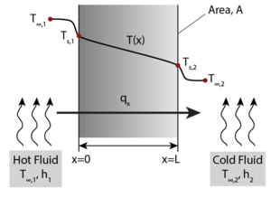
Fourier’s Law provides an empirical description of conduction stating that the heat flux, q, travelling from a region of higher temperature to a region of lower temperature is equal to the product of the temperature gradient, ΔT, between the two regions and the thermal conductivity of the material, k. This means that the energy transport by conduction between two regions increases with the temperature difference between the two regions. A simple one-dimensional heat transfer case by solid-state conduction is shown with a wall exposed on one side to a hot fluid and to a cold fluid on the other side. Under steady state conditions a linear temperature gradient develops inside the wall as heat is transferred from the hot fluid through the solid wall to the cold fluid via conduction.
For a simple steady-state one-dimensional case, the differential form of Fourier's Law simplifies to:
Which, if the temperature distribution is linear, becomes:
Where \(q_x\) is the heat flux in [W/m2] in the x direction, \(\bigtriangleup T\) is the temperature gradient in [K/m] in the \(x\) direction, and \(k\) is the thermal conductivity of the material in [W/m·K].
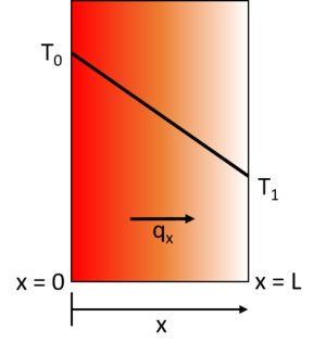
In order to understand the 1D steady-state temperature distribution through a part, where one side side is hotter than the other, the differential form of qx must be substituted into the fundamental energy equation. Take the following example, where an infinitely long wall is heated from one side.
\(-\frac{\partial q}{\partial x}-\frac{\partial q}{\partial y}-\frac{\partial q}{\partial z}+\dot Q_{gen}-\dot Q_{cons}=\rho c_p\frac{\partial T}{\partial t}\)
For this case, the one-dimensional form of the energy equation, with no internal heat generation (\(\dot Q_{gen}\)) or accumulation (\(\dot Q_{cons}\)), i.e., steady state, becomes:
Which gives:
Integrating the above equation and solving for the boundary conditions (i.e. T(0) = T0 and T(L) = T1) yields:
Under steady-state conditions, the temperature profile increases linearly from T0 to T1.
Transient conduction[edit | edit source]
Transient (non-steady state) conduction involves heat capacity (\(c_p\)), density (\(\rho\)), thermal diffusivity (\(\alpha\)), and a rate term.
The thermal diffusivity is defined as\[\alpha=\frac{k}{\rho c_p}\]
Where,
\(k=\)thermal conductivity [W/m·K]
\(\rho=\)density [kg/m3]
\(c_p=\)specific heat capacity [J/kg·K]
The grouping of terms \(\rho c_p\) is volumetric heat capacity [J/m3·K]
The SI units used of thermal diffusivity are then [m2/s]. Thermal diffusivity varies from low values of about 0.1 10-6 m2/s to high values of about 1000 10-6 m2/s. When the thermal conditions around a material changes, a material with a high thermal diffusivity will reach thermal equilibrium faster than a material with a lower thermal diffusivity.
Thermal diffusivities of some common materials used in composite manufacturing are given in the following table:
| Material | Thermal Diffusivity [10-6 m2/s] |
|---|---|
| Aluminum | 68.9 |
| Steel | 14.2 |
| Invar | 2.7 |
| Carbon-Epoxy Composite | 0.5 |
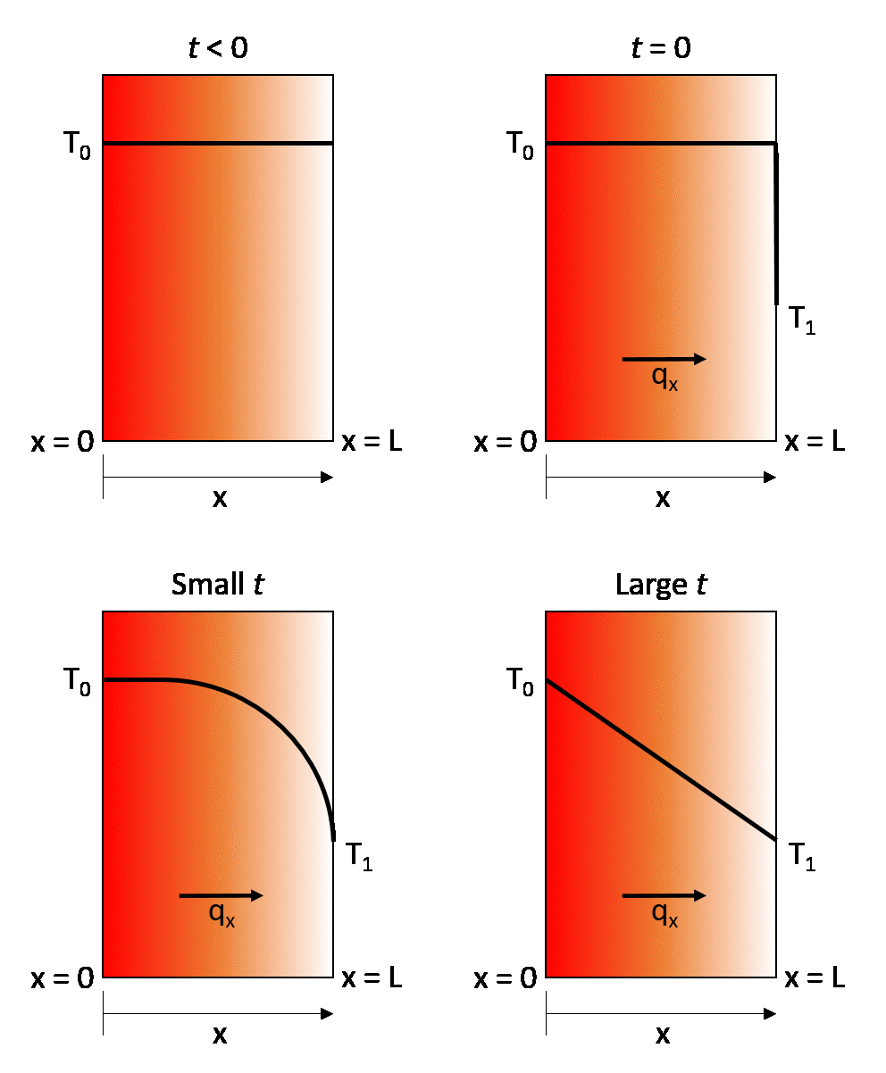
The earlier described steady-state example can be turned into a transient state conduction case by considering that the same wall is initially at a temperature T0. throughout, and then that at time t = 0 its right-hand wall is suddenly brought to the temperature T1. As time proceeds, the through-thickness temperature of the wall changes as heat flows in or out of the wall until eventually the linear steady-state distribution described in the previous section is achieved.
For this case, the one-dimensional form of the energy equation becomes\[-\frac{dq_x}{dx}=\rho c_p\frac{\partial T}{\partial t}\]
Therefore,
\(\frac{d}{dx}\Biggl(k\frac{dT}{dx}\Biggr)=\rho c_p\frac{\partial T}{\partial t}\)
Which gives\[\alpha\frac{d^2T}{dx^2}=\frac{\partial T}{\partial t}\]
Where \(\alpha\) is the thermal diffusivity in [m2/s].
The rate of temperature change, and consequently the time to reach thermal equilibrium, therefore depends on the thermal diffusivity of the material.
For a composite laminate curing in an autoclave or oven, where the moving air is acting as a convective heat transfer boundary condition, graphical Heisler charts can be used to look up an approximate solution to the transient conductivity equation for the internal temperature profile of the laminate. Modern technology also allows an exact solution to be obtained using a number of available math or finite element software packages [2]. Alternatively, a simplified closed-form approximation developed by Rasekh et al. [3] can also be used. For more information regarding using this approximation, please see the paper by Rasekh et al. here.
Related pages
References
- ↑ [Ref] Gaskell, David R. (1992). An Introduction to Transport Phenomena in Materials Engineering. Macmillan Publishing Company. ISBN 0023407204.CS1 maint: uses authors parameter (link) CS1 maint: date and year (link)
- ↑ [Ref] Slesinger, Nathan Avery (2010). Thermal Modeling Validation Techniques for Thermoset Polymer Matrix Composites (Thesis). doi:10.14288/1.0071063.CS1 maint: uses authors parameter (link)
- ↑ [Ref] Rasekh, Ali et al. (2004). Simple Techniques for Thermal Analysis of the Processing of Composite Structures. Society for the Advancement of Material and Process Engineering.CS1 maint: extra punctuation (link) CS1 maint: uses authors parameter (link) CS1 maint: date and year (link)
| About | Help |
Welcome
Welcome to the CKN Knowledge in Practice Centre (KPC). The KPC is a resource for learning and applying scientific knowledge to the practice of composites manufacturing. As you navigate around the KPC, refer back to the information on this right-hand pane as a resource for understanding the intricacies of composites processing and why the KPC is laid out in the way that it is. The following video explains the KPC approach:
Understanding Composites Processing
The Knowledge in Practice Centre (KPC) is centered around a structured method of thinking about composite material manufacturing. From the top down, the heirarchy consists of:
- The factory
- Factory cells and/or the factory layout
- Process steps (embodied in the factory process flow) consisting of:
The way that the material, shape, tooling & consumables and equipment (abbreviated as MSTE) interact with each other during a process step is critical to the outcome of the manufacturing step, and ultimately critical to the quality of the finished part. The interactions between MSTE during a process step can be numerous and complex, but the Knowledge in Practice Centre aims to make you aware of these interactions, understand how one parameter affects another, and understand how to analyze the problem using a systems based approach. Using this approach, the factory can then be developed with a complete understanding and control of all interactions.
Interrelationship of Function, Shape, Material & Process
Design for manufacturing is critical to ensuring the producibility of a part. Trouble arises when it is considered too late or not at all in the design process. Conversely, process design (controlling the interactions between shape, material, tooling & consumables and equipment to achieve a desired outcome) must always consider the shape and material of the part. Ashby has developed and popularized the approach linking design (function) to the choice of material and shape, which influence the process selected and vice versa, as shown below:
Within the Knowledge in Practice Centre the same methodology is applied but the process is more fully defined by also explicitly calling out the equipment and tooling & consumables. Note that in common usage, a process which consists of many steps can be arbitrarily defined by just one step, e.g. "spray-up". Though convenient, this can be misleading.
Workflows
The KPC's Practice and Case Study volumes consist of three types of workflows:
- Development - Analyzing the interactions between MSTE in the process steps to make decisions on processing parameters and understanding how the process steps and factory cells fit within the factory.
- Troubleshooting - Guiding you to possible causes of processing issues affecting either cost, rate or quality and directing you to the most appropriate development workflow to improve the process
- Optimization - An expansion on the development workflows where a larger number of options are considered to achieve the best mixture of cost, rate & quality for your application.
To use this website, you must agree to our Terms and Conditions and Privacy Policy.
By clicking "I Accept" below, you confirm that you have read, understood, and accepted our Terms and Conditions and Privacy Policy.


