Porosity - A335
| Porosity | |
|---|---|
| Document Type | Article |
| Document Identifier | 335 |
| Themes | |
| Tags | |
| Prerequisites | |
Introduction[edit | edit source]
Porosity in composite material is a manufacturing outcome defined as the absence of resin in locations that should be occupied by resin. Porosity is synonymous with voids, bubbles or pin holes. It is a very common defect that can occur in a wide range of parts made with various manufacturing methods. The majority of porosity in composite parts is induced during the manufacturing process. Entrapped air within laminates during layup, resin outgassing from volatiles, and poor resin infiltration are among the known causes of porosity [1].
The manufacturing process itself, whether it be vacuum infusion, resin transfer molding, wet layup, prepreg processing, or compression molding, plays a significant role in porosity development. Each step prior to thermal transformation can potentially contribute to porosity, including storage conditions and formulation methods. However, after thermal transformation, the material is vitrified, and further porosity induction is highly unlikely. Porosity management is very specific to the manufacturing process, manufacturing step and porosity sources and sinks.
Significance[edit | edit source]
Porosity can dramatically reduce the composite structure’s performance, especially at locations where resin is transferring load. It is shown that a porosity volume content of 2% can causes 10% - 20% reduction in interlaminar strength, depending on the fibre volume fraction and distribution/location of the porosity[2]. Porosity can also act as a stress concentrator which facilitates matrix cracking. Consequently, strict rules are imposed on the allowable level of porosity in parts being used in primary aerospace structures, which is typically at 2%.
Scope[edit | edit source]
The sources and mechanisms that cause porosity are complex, and process dependent. This page aims to explain the different types of porosities, how they form (sources) and how to mitigate them (sinks). The list of porosity sources and sinks mentioned on this page are meant to be generic and not limited to any specific manufacturing process.
Surface vs bulk porosity[edit | edit source]
Porosity in composite material can be categorized into surface porosity or bulk porosity. Surface porosity is visible pin holes or dimples on the part surface. Though it can degrade the material's aesthetic and potentially impact its aerodynamic performance, surface porosity typically does not substantially affect the structural integrity of the material. It may, however, pose challenges for applying finishes, such as paint, due to the irregularities on the surface.
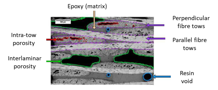
Bulk porosity refers to internal porosity that is not on the surface of the part. Bulk porosity can be further categorized into different types based on its location within the material. Intratow porosity, for instance, occurs within the individual fibres of a material, possibly resulting from incomplete saturation or the formation of internal bubbles. Intertow porosity, conversely, is found between the tows. Another type, interlaminar porosity, arises between the layers or plies of material stacked upon each other. Finally, resin porosity is observed within the resin used in composite materials.
Porosity sources and sinks[edit | edit source]
Porosity in composites is typically conceptualized as a dynamic interplay between sources and sinks. Sources are the mechanisms that introduce porosity, such as entrapped air during lamination or off-gassing from the resin under vacuum conditions. Conversely, sinks refer to mechanisms that mitigate or eliminate porosity, including gas transport, which expels entrapped air or volatiles, and void shrinkage or collapse, compressing the volume of porosity. Ideally, these sources and sinks should be balanced, resulting in an acceptable amount of porosity. The following text provides an exhaustive list of porosity sources and sinks. Detailed explanations and examples for each source will be provided for better understanding. The goal is to enable readers to identify potential sources relevant to their specific applications and subsequently manage porosity using suitable porosity sinks. Readers are encouraged to contribute to this collective knowledge by suggesting any overlooked sources or sinks through the "Feedback" feature available on this page.
Porosity sources[edit | edit source]
- Fibre/resin incompatibility
- Entrapped gas in setup and consumables
- Resin over-bleeding/lack of resin
- Empty volume from geometry (bridging, ply drop off)
- Tool dimensional error
- Core absorbing resin causing face sheet to starve
- Face sheet dimpling and pull away from the tool
- Moisture absorbed in core
- Undissolved gases and volatiles in the resin (visible bubbles)
- Resin shrinkage
- Lack of consolidation
- Tool/bag vacuum leak
- Outgassing of absorbed volatiles in the fibre
- Outgassing of dissolved gases and volatiles in the resin
- Moisture in the fibre
- Moisture in the resin
- Formation of cure reaction by-products
- Issues with resin flowing through fibre bed
- Insufficient gas transport within the laminate
Porosity sinks[edit | edit source]
- Resin formulation
- Prepreg design (architecture, degree of impregnation)
- Resin/prepreg storage and handling conditions
- Degassing, vacuum removing air, moisture and volatiles in resin
- Material deposition techniques
- Geometry design (avoiding sharp corners, and aggressive ply drop offs)
- Proper amount of bleed and breathing using consumables
- Debulking, vacuum removing air, moisture and volatiles in the prepreg laminate and resin
- Eliminating vacuum leaks in tool and vacuum bag setup including consumables
- Eliminating gaps between tool and part (fibre bridging, underfill in match-die)
- Pressure (from roller/autoclave/press) to provide consolidation
- Control resin flow speed (pressure differential)
- Control resin flow directions (injection strategies)
- Control thermal history (out time, cure cycle) to reduce moisture driven bubble growth
Deep dive into porosity sources[edit | edit source]
Fibre/resin incompatibility[edit | edit source]
The issue of resin-fibre incompatibility can contribute significantly to porosity in composite materials. A common example is observed in the use of chopped strand mat, where a binder material is employed to hold the fibre together. Typically, this binder is designed to dissolve in the presence of styrene found in polyester or vinyl ester resins. When such a resin is applied, it breaks down the binder, allowing the fibre to move relative to each other and the fibre bed to be compacted. However, epoxy, which does not contain styrene, does not break down the binder, thereby potentially causing porosity.
In a more generic sense, fibre and resin can also be incompatible for a given process if they do not meet the process requirements. For example, for an infusion process, if the resin to be infused is very viscous and the dry fibre bed is tightly packed, the resin will flow very slowly and could gel before infiltrating the whole part. The resin and the fibre are considered to be incompatible for the process.
This incompatibility between the fibre and resin primarily influences porosity during the material deposition stage, where the resin and fibre are combined. It is pertinent in all processes employing incompatible resin and fibre combinations. Although the chopped strand mat example with epoxy is used here, other scenarios could include incompatible sizing on the fibre or a particular resin chemistry.
Mitigation of this porosity, or porosity sinks, includes careful resin formulation. Material deposition techniques and consolidation pressure also have roles in reducing this form of porosity, as they can influence the distribution and volume of the created porosity.
Entrapped gas in setup and consumables[edit | edit source]
In composites manufacturing, porosity can arise from a poorly designed mould that leads to air or gas entrapment. This phenomenon can happen in compression moulding, injection moulding and resin transfer moulding. As the resin is injected, the air within the mold must escape. Absence of or clogged vents and outlets can result in trapped air, manifesting as porosity in the final product. Similar air entrapment can occur in the consumables during an infusion process. For instance, trapped air could be introduced through an air inlet tube during infusion if the tube is temporarily removed and then reinserted.
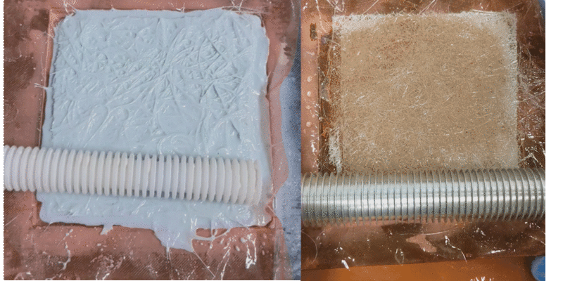
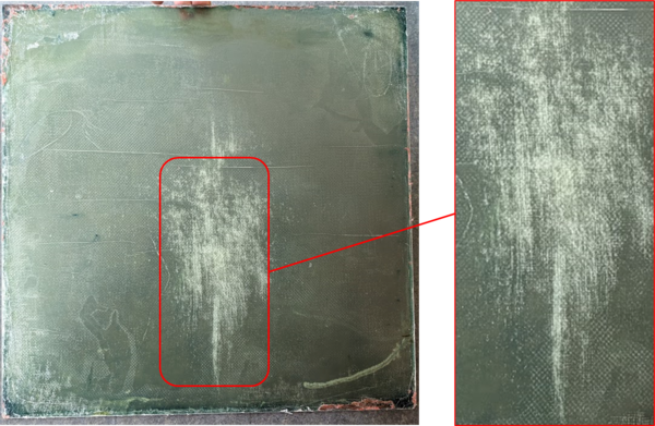
This entrapped air typically becomes problematic during the material deposition stage. Mitigation of entrapped gas—and consequently porosity—can be achieved through careful material deposition techniques and part shape design. For example, a case study of a 15x15 inch square plate created through wet layup and hot press compression molding resulted in trapped porosity at its center. This is likely due to the pressing action sealing off the perimeter, preventing the escape of air from the laminate. As the resin saturates the fibre, it obstructs the air path leading to its entrapment and resultant porosity as shown in the figure.
Resin over-bleeding[edit | edit source]
Resin bleed or over-bleeding in composites manufacturing refers to a situation where excess resin is removed after the fibre and resin mixture is prepared. This can be the result of a bleeder or breather cloth absorbing too much resin, for example. Certain prepregs are specifically designed to bleed a pre-determined amount of resin, while others are manufactured to avoid resin bleeding entirely.
Resin over-bleeding can generate porosity through two primary mechanisms. The first mechanism involves excessive removal of resin, leading to a resin-starved laminate that is unable to fill the entire volume between the fibre. The second mechanism is prevalent in autoclave cured prepregs where over-bleeding results in a reduction of resin pressure. As the resin is removed, the fibre bears a greater load and the remaining resin is subjected to lower pressure, potentially even a vacuum pressure. This low-pressure environment can induce off-gassing from materials within the resin, leading to bubble formation, which ultimately manifests as porosity.
This porosity-inducing phenomenon is observed mainly during the material deposition stage, and the thermal transformation stage. During the curing process, the viscosity of the resin decreases with increasing temperature, allowing for resin to bleed away more easily. Processes affected by this phenomenon include any that involve resin loss, such as processing prepregs, or wet layups with a vacuum bag. Resin over-bleeding can also be significant in sandwich structures utilizing a core material where resin can be absorbed into the core.
To mitigate porosity caused by resin over-bleeding, careful material deposition techniques should be employed. This includes the appropriate application of the bleeder cloth and usage of suitable consumables such as the correct bleeder cloth or bleeder materials.
Empty space from geometry and tool dimensional error[edit | edit source]
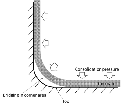
Porosity can also originate from empty spaces caused by geometric factors, including bridging, ply drop-offs, or dimensional errors in tools. Bridging refers to a situation where the fibre does not conform accurately to the tool geometry, leading to an excess of thickness in the area with reduced fibre content. The resulting porosity can either stem from the resin's inability to fill this area or from the off-gassing effect when the area, filled by less resin, is under lower pressure.
This phenomenon can also occur in the context of ply drop-offs, as demonstrated in an experiment involving a relatively stiff caul plate and ply drop-offs at various positions. These drop-offs create sections of lower pressure, which could potentially lead to porosity if the resin does not adequately flow into and fill this volume.
These porosity-inducing occurrences are typically encountered during the material deposition stage and could affect any process characterized by such geometric situations. To mitigate this, strategies include altering material deposition techniques, refining shape design to avoid inducing factors like sharp corners or aggressive ply drop-offs, eliminating gaps between the tool and the part, and applying appropriate consolidation pressure to ensure better fibre conformation and prevent bridging.
Another related concern is tooling dimensional errors. If gaps between the tool and the laminate are not properly filled, this empty volume tends to attract resin flow, leading to an over-bleeding condition. Processes susceptible to this situation, occurring during both material deposition and thermal transformation stages, require similar mitigation strategies as mentioned previously.
Porosity in Sandwich Structure[edit | edit source]
When discussing sandwich structures in the context of composite materials, several sources of porosity become relevant, and it is advantageous to address them collectively.
One of the mechanisms involves core materials, such as open-cell foam or Balsa, which can absorb resin. This absorption process leads to an over-bleeding situation wherein these "thirsty" materials, when combined with fibre and resin, extract excess resin, rendering the fibre-resin composite considerably drier.
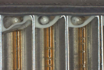
Another potential cause of porosity arises when the adhesive experiences low resin pressure. As demonstrated in one of the accompanying images, when the resin is subjected to reduced pressure, volatiles within the material can begin to off-gas, creating bubbles and subsequently leading to porosity.
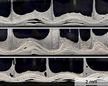
Dimpling of the face sheet or pulling away from the tool also contributes to porosity formation. As illustrated in the micrograph, this is visible as the plies appear to be pulling away and dimpling between the honeycomb core walls. This displacement causes the porosity to form between the laminate layers. An accompanying image further highlights how the laminate becomes wavy, showcasing a combination of porosity and dimpling as defects.
Additionally, moisture absorbed in the core can migrate into the resin during the process, creating porosity, often at the core-fibre interface. It's important to note that these mechanisms are presented in a high-level, superficial context because sandwich structures or cores can comprise various types of core materials. These could range from foam or balsa wood to honeycomb structures, and even within the honeycomb category, materials like Nomex honeycomb, an aramid fibre with phenolic resin, or aluminum honeycomb exist.
Undissolved gases and volatiles in the resin (visible bubbles)[edit | edit source]
Another source of porosity within composite materials, which may seem more intuitive than other mechanisms, is the presence of undissolved gases and volatiles in the resin, visible as bubbles during processing. If these gaseous inclusions aren't collapsed or adequately removed, they remain suspended in the resin, ultimately becoming trapped within the material upon curing.
The manufacturing stages that contribute to this issue include the resin formulation phase, where certain resins may have a higher propensity to trap bubbles. The material deposition stage also plays a role, which will be discussed in subsequent sections, as well as the thermal transformation phase, during which the bubbles become permanently trapped within the material.
The processes most affected by this form of porosity are those that involve the mixing of liquid resin, including wet layup, infusion, and spray-up. Prepreg processes are less likely to be affected.
Mitigation strategies or 'sinks' for these bubbles heavily rely on material deposition techniques. A method such as degassing can prove effective in eliminating these bubbles and removing their contents. This topic is of particular importance for vacuum infusion and resin transfer molding processes, and will be explored in greater detail in the subsequent part of this discussion. In summary, the undissolved gases and volatiles constitute a notable contributor to porosity in composite materials.
Resin shrinkage[edit | edit source]
Resin shrinkage is another porosity inducing mechanism to consider. As the polymer and hardener undergo curing, the resin experiences a phenomenon known as 'cure shrinkage'. This is a slight decrease in the volume of the resin, often leading to residual stress due to the lack of a corresponding shrinkage in the fibre, which creates a stress disparity between the two components.
An interesting consequence of this resin shrinkage is the potential expansion of the porosity bubble. An experiment conducted by Mohammad Moshini in our laboratory sought to observe and quantify this phenomenon. In the experiment, neat resin with minuscule bits of fibre acting as tracers was observed under a microscope. A bubble observed at the beginning of the curing process was found to increase in size over time as the resin shrunk around it. The void, with no inherent structure or stiffness, was able to increase in size due to the resin shrinkage.
Within a fibre bed, this phenomenon may not be quite as pronounced, as the fibre's presence affects how porosity increases in size, but the fundamental mechanism is the same. This process typically occurs during the thermal transformation stage when cure shrinkage happens. Any process could potentially be susceptible to this phenomenon, and most mitigation strategies would apply. The main concern is that cure shrinkage can potentially amplify the size of the bubbles within the porosity, hence increasing porosity.
Lack of or insufficient consolidation[edit | edit source]
The final porosity source to discuss in composite materials pertains to the lack of consolidation. Insufficient consolidation signifies that the fibre and resin are not adequately held together under pressure, leading to porosity. By applying more pressure, we can push out or collapse the bubbles back into the resin, subsequently reducing porosity.
We observe this phenomenon in both material deposition and thermal transformation stages. Almost every process requires some form of consolidation. In the case of a wet layup without a vacuum bag, gravitational force provides the necessary consolidation. However, in other scenarios, one might employ a vacuum bag using vacuum pressure, the pressure of a resin transfer molding (RTM) mold, or a press for consolidation. Every process includes some degree of consolidation.
Various factors, including material deposition techniques, part design, and the amount of pressure applied through the chosen consolidation method, can impact the degree of porosity observed. A classic example can be observed in pre-impregnated (prepreg) composite fabrics processed in and out of an autoclave. An autoclaved prepreg typically exhibits low porosity, as seen in the left-hand image, with minimal porosity traces. However, a non-autoclaved prepreg tends to show more porosity, as illustrated on the right.
This example does not suggest that all non-autoclaved prepregs will display higher porosity. There are materials specifically designed for out-of-autoclave use that produce very low porosity parts. However, this comparison underscores the idea that autoclave pressure provides significant consolidation pressure on the material. Conversely, out-of-autoclave processes, with only atmospheric pressure from the vacuum bag, exert less pressure, which can potentially lead to higher porosity levels.
Tool/bag/vacuum leak[edit | edit source]
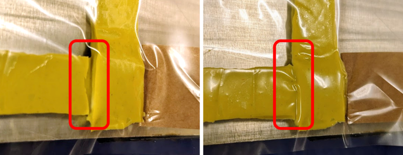
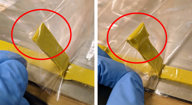
Porosity in composite materials can be induced by tool, bag, or vacuum leaks, whereby air or gas infiltrates the system and subsequently remains trapped, contributing to porosity. These leaks can arise from various sources, such as tacky tape pleats, overlaps, inlets/outlets, and instances where objects pass through, including backing tape, peel ply, or reinforcement fibre. Vacuum bag punctures and consumable leaks, such as an inlet tube leak, are further potential sources. Additionally, tool leaks due to damage, subpar welds, poorly sealed tool surfaces, or even tooling material permeability can contribute to porosity.
These leaks generally occur and affect the final porosity level during two stages in the manufacturing process: material deposition and thermal transformation. This issue predominantly affects all closed mold processes that involve a vacuum.
To mitigate these leaks and hence porosity, several 'sinks' can be implemented. These include refining material deposition techniques and eliminating vacuum leaks in tool and vacuum bag setup, inclusive of consumables. Furthermore, conducting a leak test is an effective preventative measure to detect and rectify any potential leaks, thus reducing the likelihood of porosity due to tool, bag, or vacuum leaks.
Outgassing[edit | edit source]
Outgassing, a phenomenon involving the release of gas prior to resin gelation and vitrification, is a significant contributing factor to porosity in composite materials. Its implications can vary, as evidenced by differing outcomes in epoxy flooring and space applications. The sources of outgassing can also be influenced by temperature. These gases may include air, moisture, low molecular weight volatiles, and curing by-products. They could originate from various sources such as absorbed volatiles in the fibre, dissolved gases and volatiles in the resin, moisture in both the fibre and resin, as well as from the formation of cure reaction by-products. Especially under vacuum environment, evaporating moisture can serve as nucleation sites, fostering porosity development during cure. This moisture could either be sourced from the fibre or the resin. Complete moisture extraction is typically impractical.
The effect of moisture on final porosity levels can be observed in various stages of the manufacturing process, including storage, formulation (mixing), material deposition, and thermal transformation. Moisture potentially affects all processes involved in manufacturing.
To mitigate porosity due to moisture, several strategies can be employed. These involve degassing and debulking, which involve the use of a vacuum to remove air, moisture, and volatiles in resin or the prepreg laminate. Moreover, controlling thermal history, such as out time and cure cycle, can significantly reduce moisture-driven bubble growth.
Proper storage and handling are crucial to maintaining composite material quality. Prepregs, for instance, require cold transportation and storage, preventing premature advancement of cure, which can lead to less desirable handling properties, and even affect cured ply properties. It's also important to note that many of these materials have defined shelf lives, typically around one year. Use of expired or improperly stored and handled material can negatively impact the final part's quality and the ease of manufacture.
Moisture poses a significant threat to prepregs, hence necessitating moisture control during transportation and storage. Moisture can condense on the raw materials' exterior surface and absorb into the resin, particularly when packages are opened immediately after removing them from the freezer. Excess moisture within prepregs can considerably degrade the composite part's final properties. Moisture in the layup can vaporize during heating, resulting in excess porosity in the final part, indicating that even minor amounts of water can lead to substantial porosity.
Issues with resin flowing through fibre bed[edit | edit source]
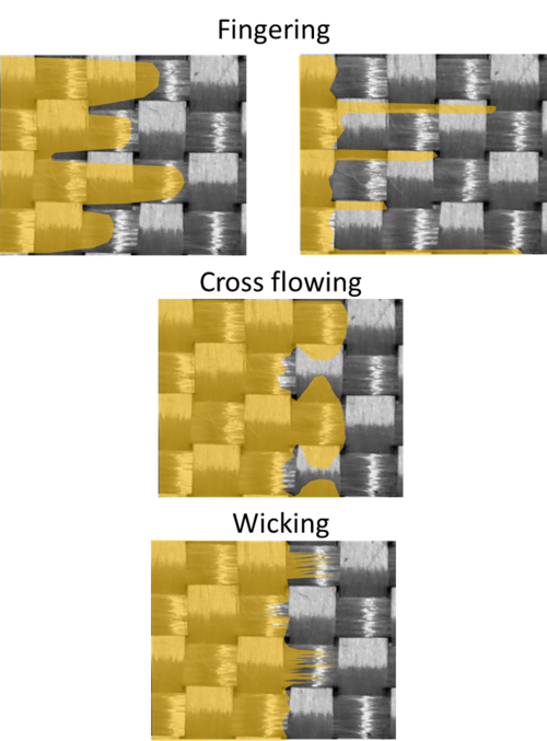
In the context of resin flow through the fibre bed during composite materials manufacturing, it is essential to understand two distinct types of flows: the flow through the gaps between the fibre tows macroscopic flow) and the flow directly within the fibre tows (microscopic). Within these two types of flow, three unique phenomena emerge, namely, fingering, cross-flowing, and wicking.
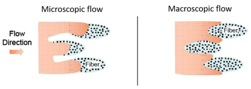
Fingering characterizes the lead-lag pattern observed in the resin flow front, mimicking the shape of fingers. The leading flow front may be situated between tows, while the lagging flow front could be found within tows, or vice versa. Cross-flowing, on the other hand, involves resin flowing transversely away from the primary flow direction, creating a lateral dispersion. Wicking refers to the partial wetting of the fibre bed ahead of the flow front, in which resin is drawn forward due to the capillary pressure.
These phenomena, individually or combined, can trap gas and form porosity, which can be trapped in between or within tows. The resultant gas bubbles may be eliminated after the mold filling process. The emergence of fingering, cross-flowing, and wicking is dependent on several parameters. These parameters include fibre architecture, resin flow speeds, viscous drag/forces, consumables and part geometry.
Fibre architecture[edit | edit source]
As the resin flows through the fibre bed during composites manufacturing, the fibre architecture plays a crucial role in determining the resultant flow pattern. This architecture essentially represents what the resin interacts with or "sees" during its movement. A host of features, including gaps, stitches, fibre count per tow, symmetry, tow direction, crimps, and binder particles, can significantly impact the trajectory of the resin flow.
To illustrate, gaps and crimps located between the fibre tows typically exhibit a higher permeability compared to the fibre tows themselves. Consequently, the resin tends to preferentially flow into these gaps to occupy the available empty space. Similarly, stitches also influence the flow pattern. In fabrics featuring asymmetric stitches on their top and bottom sides (such as single and double stitches), varying flow patterns may be observed on each side due to the distinctive structural characteristics.
Resin flow speeds[edit | edit source]
Resin flow speed plays a significant role in determining the flow pattern and part final porosity level. The flow speeds, in turn, depend on resin viscosity, pressure differential, permeabilities of both the tow and the overall porous fibre bed, and capillary pressure. It is shown at low flow rates, the flow within the fibre tows leads the flow between the tows. Conversely, at a high flow rate, the flow between the fibre tows leads the flow within the tows[4]. Consequently, at low flow rates, porosity is more likely to exist in the inter-tow region whereas at higher flow rates porosity can be trapped in intra-tow region.
Typically flow speed refers to the speed of the primary flow front. This flow front speed can be manipulated by either controlling the inlet flow rate or the use of consumables such as flow mesh to alter the overall permeability. The flow front speed can be used as a general flow rate indicator. However, it is crucial to note that flow speeds on a smaller scale are not static values, but vary constantly within a laminate. Each type of flow has its own speed, which changes as the resin flows from the inlet to the outlet.
Resin viscosity and viscous forces/drag[edit | edit source]
The pattern of the resin flow front, in addition to the resin flow speed, is significantly influenced by the resin viscosity and its interaction with the fibre bed. Factors such as surface tension, wetting force, and contact angle play a significant role in this interaction. Resins possessing low viscosity and good wetting capabilities can permeate the fibre tows easily, leading to pronounced fingering and wicking patterns at low flow rates. At higher flow rates, the resin flow interstitially between the fibre tows and lead the flow within the tows, and the low viscosity resin can also quickly infiltrate the fibre tow to maintain pace with the flow front. In contrast, a high-viscosity resin with less wetting capabilities will flow around the tows at a high flow rate, with significant lag in penetrating the tows. This results in a big gap (distance) between the flow front and the region of complete fibre bed saturation, thereby entrapping bubbles within the tow and contributing to the final part's porosity.
The concept of viscous drag in the context of liquid moulding composite manufacturing pertains to the resistance experienced by the fibre bed as the viscous resin flows through it. The drag force holds significance since after the mould is filled, or the part is infused, it's feasible to inject or flush the resin through at a higher flow rate to eliminate bubbles post-formation, a process known as flushing, bleeding, or purging. This method primarily involves movement, elongation, and breaking of bubbles, with intermittent recombination, intending to eliminate or reduce porosity. The drag force relies on variables such as resin viscosity, fibre sizing, surface tension, consumables like peel ply or flow mesh, release agents, and part geometry.
Part geometry[edit | edit source]
Part geometry influences the resin flow pattern in a more intuitive way. Features such as thickness change, corners and contours create different resin flow paths. In these areas, the resin may either accelerate, slow down, or be blocked entirely, leading to voids or regions of higher resin concentration.
For example, in areas of a part that are narrower or have smaller cross-sectional areas, the resin flow rate can increase due to this constriction. This accelerated flow could potentially leave behind voids as discussed in sections above. On the contrary, in wider or thicker sections, the resin may slow down, leading to different flow front patterns.
Furthermore, vertical sections or inclines in the part geometry can also introduce challenges due to the effect of gravity on resin flow. These areas may require careful control of flow rates or the use of specific infusion strategies to ensure proper wet-out of the fibre and prevent voids or resin-rich areas.
Overall, the geometry of a part requires careful consideration and often necessitates tailored resin infusion strategies to ensure an optimal, void-free composite. Visit shape development for more information.
Insufficient gas transport within the laminate[edit | edit source]
Gas transport within a laminate can affect porosity in a composite material. If gas that is contained within a laminate cannot escape then it can lead to porosity. Evacuating this gas through gas transport mechanisms can lead to less porosity. The main mechanism is gas travelling through flow paths along the fibre, often within the tows. As the resin saturates the tows during the process it blocks these paths off and does not allow gas to pass through, effectively trapping it within the composite.
Related pages
| Page type | Links |
|---|---|
| Introduction to Composites Articles | |
| Foundational Knowledge Articles | |
| Foundational Knowledge Method Documents | |
| Foundational Knowledge Worked Examples | |
| Systems Knowledge Articles | |
| Systems Knowledge Method Documents | |
| Systems Knowledge Worked Examples | |
| Systems Catalogue Articles | |
| Systems Catalogue Objects – Material | |
| Systems Catalogue Objects – Shape | |
| Systems Catalogue Objects – Tooling and consumables | |
| Systems Catalogue Objects – Equipment | |
| Practice Documents | |
| Case Studies | |
| Perspectives Articles |
|
References
- ↑ [Ref] Fernlund, G et al. (2016). "Causes and remedies for porosity in composite manufacturing". 139 (1). Institute of Physics Publishing. doi:10.1088/1757-899X/139/1/012002. ISSN 1757-8981. Cite journal requires
|journal=(help)CS1 maint: extra punctuation (link) CS1 maint: uses authors parameter (link) - ↑ [Ref] Bowles, Kenneth J.; Frimpong, Stephen (1992). "Void Effects on the Interlaminar Shear Strength of Unidirectional Graphite-Fiber-Reinforced Composites". 26 (10). doi:10.1177/002199839202601006. ISSN 0021-9983. Cite journal requires
|journal=(help)CS1 maint: uses authors parameter (link) - ↑ [Ref] Leclerc, Jean Sébastien; Ruiz, Edu (2008). "Porosity reduction using optimized flow velocity in Resin Transfer Molding". 39 (12). Elsevier Ltd. doi:10.1016/j.compositesa.2008.09.008. ISSN 1359-835X. Cite journal requires
|journal=(help)CS1 maint: uses authors parameter (link) - ↑ [Ref] Molnar, J. A. et al. (1989). "Liquid flow in molds with prelocated fiber mats". 10 (6). doi:10.1002/pc.750100605. ISSN 0272-8397. Cite journal requires
|journal=(help)CS1 maint: extra punctuation (link) CS1 maint: uses authors parameter (link)
| About | Help |
Welcome
Welcome to the CKN Knowledge in Practice Centre (KPC). The KPC is a resource for learning and applying scientific knowledge to the practice of composites manufacturing. As you navigate around the KPC, refer back to the information on this right-hand pane as a resource for understanding the intricacies of composites processing and why the KPC is laid out in the way that it is. The following video explains the KPC approach:
Understanding Composites Processing
The Knowledge in Practice Centre (KPC) is centered around a structured method of thinking about composite material manufacturing. From the top down, the heirarchy consists of:
- The factory
- Factory cells and/or the factory layout
- Process steps (embodied in the factory process flow) consisting of:
The way that the material, shape, tooling & consumables and equipment (abbreviated as MSTE) interact with each other during a process step is critical to the outcome of the manufacturing step, and ultimately critical to the quality of the finished part. The interactions between MSTE during a process step can be numerous and complex, but the Knowledge in Practice Centre aims to make you aware of these interactions, understand how one parameter affects another, and understand how to analyze the problem using a systems based approach. Using this approach, the factory can then be developed with a complete understanding and control of all interactions.
Interrelationship of Function, Shape, Material & Process
Design for manufacturing is critical to ensuring the producibility of a part. Trouble arises when it is considered too late or not at all in the design process. Conversely, process design (controlling the interactions between shape, material, tooling & consumables and equipment to achieve a desired outcome) must always consider the shape and material of the part. Ashby has developed and popularized the approach linking design (function) to the choice of material and shape, which influence the process selected and vice versa, as shown below:
Within the Knowledge in Practice Centre the same methodology is applied but the process is more fully defined by also explicitly calling out the equipment and tooling & consumables. Note that in common usage, a process which consists of many steps can be arbitrarily defined by just one step, e.g. "spray-up". Though convenient, this can be misleading.
Workflows
The KPC's Practice and Case Study volumes consist of three types of workflows:
- Development - Analyzing the interactions between MSTE in the process steps to make decisions on processing parameters and understanding how the process steps and factory cells fit within the factory.
- Troubleshooting - Guiding you to possible causes of processing issues affecting either cost, rate or quality and directing you to the most appropriate development workflow to improve the process
- Optimization - An expansion on the development workflows where a larger number of options are considered to achieve the best mixture of cost, rate & quality for your application.
To use this website, you must agree to our Terms and Conditions and Privacy Policy.
By clicking "I Accept" below, you confirm that you have read, understood, and accepted our Terms and Conditions and Privacy Policy.


