Foam - A328
| Foam | |
|---|---|

| |
| Document Type | Article |
| Document Identifier | 328 |
| Relevant Class |
Material |
| Tags | |
Introduction[edit | edit source]
Foam as a core material was developed to be used as a lightweight alternative to natural core materials (various woods). Compared to wood cores, foam in general has less local density variations and less moisture absorption. Another advantage of foam compared to wood or honeycomb cores is the potential to be thermoformed into complex geometry while maintaining relatively uniform properties. While wood or honeycomb can be formed or machined into shape, the process may be more complicated and expensive. Typically, the properties of foam core are not as good as honeycombs but foam is more economical. It is widely used in marine, wind energy and transportation applications.
Almost all polymer (uncross-linked thermoplastic and cross-linked thermoset) can be made into a foam with proper foaming or blowing agents. Thermoset generally has better mechanical properties while thermoplastic foams are more formable. Thermoset foams can also be lightly cross-linked to achieve higher formability. Foam density is usually measured in pounds per cubic foot (pcf) or kilogram per cubic meter (kg/m3). Foam core density can range from 2 to 40 pcf.[1]
Scope[edit | edit source]
Although metallic and glass foam core exist, this page focuses on polymer foam core materials. The difference between open-cell and closed-cell foam is discussed, then various manufacturing processes for foam and common foam core materials are covered.
Significance[edit | edit source]
As with other core materials, the purpose of the foam is to increase the thickness (thus bending stiffness) of the sandwich structures without a significant increase in weight. Other beneficial functions such as acoustic or heat insulation and damping may also be achieved thanks to the properties specific to a type of foam. Because almost any polymer can be made into foam, compounding with the various manufacturing techniques, foams are available in a wide variety of options. Uncross-linked thermoplastic vs cross-linked thermoset, cell structure (opened-cell vs closed-cell), density, rigid/flexible/rubbery among numerus other properties[2]. Designers should understand the implications of these foam parameters when selecting foams to fulfill the functions and requirements of the to-be-designed product.
Manufacturing of foam cores[edit | edit source]
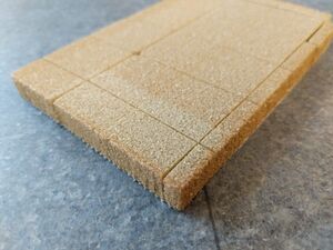
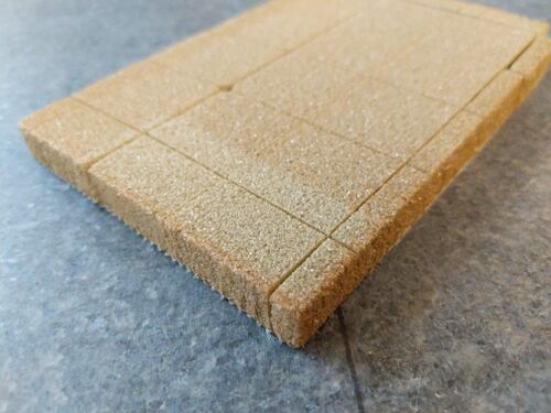
Foam can come in either two-part liquids for foam-in-place applications or pre-expanded block form. The two-part liquids are mixed and poured into a mould where the mixture expands into the desired shape whereas the pre-expanded blocks can be bonded together, then formed or machined into shape. Foam can also come in flexible sheet form where the small blocks are held by a fabric scrim backing, similar to flexible balsa sheets.
Polymer foam is produced by mixing the liquid polymer with the proper foaming or blowing agents. The mixture is poured into a mould and cured with heat and pressure. The resulting rubbery conglomeration is then heated again with a second mould in an expansion chamber (with hot water or steam). During the second heating cycle, the gas expansion pressure is controlled and the blowing agents are activated. The agents can function either physically or chemically. Physical blowing agents are gases mixed into the foam material that expand when heated. While chemical blowing agents depend on the agent decomposition during heating which produce off gases (usually nitrogen or CO2).[3]
Foam core structures[edit | edit source]
The cells of the foam core can be interconnected (open-cell) or closed and discrete (closed-cell). A core can have both open-cells and closed-cells with a percentage of each. Closed-cell foams generally have higher density and better mechanical properties than open-cell foams. Hence most foam cores used for structural applications are closed-cell. In general, the higher the foam density the higher percentage of closed cells.[4]
Open-cell foam is made with blowing agents (for example, sodium bicarbonate) that reacts with the polymer during the second heating cycle. The blowing agent "eats through" the polymer and creates an interconnected network of gas pockets. Closed-cell foams on the other hand are made with blowing agents that does not degrade the foam's cell structure, leaving gas pockets discrete.[4] Some characteristics of open and closed cell foams are listed below:
Open-cell foams are:
- softer and more springy (returns to original shape once deformed)
- breathable, allows air or other fluids to pass through
- good for sound absorption/insulation
Closed-cell foams are:
- rigid
- less permeable
Common polymer foam materials[edit | edit source]
Polyurethane[edit | edit source]
Polyurethane (PU) foam is available in uncross-linked thermoplastic and cross-linked thermoset form with varying percentage of closed cells.[1] Mix-and-pour/foam-in-place two part thermoset polyurethane is also common for insulation applications. Depending on the polymer formulation, some PU foam can be used up to 275 °F and 350 °F, enabling them to be cured with high temperature pre-pregs in ovens and autoclaves.[5] PU foam typically has moderate mechanical properties and are prone to core-to-face sheet delaminate with age. PU foam can be easily machined to the desired shape. Hot wire cutting PU foam should be avoided since toxic fumes can be generated.[1]
Polyvinyl chloride (PVC)[edit | edit source]
Polyvinyl chloride (PVC) is the most widely used foam core materials for sandwich panels[3]. PVC foam are also available in uncross-linked thermoplastic and cross-linked thermoset form with differences in polymer formulation. Both the thermoset and thermoplastic PVC can be thermoformed and exhibit good fatigue performance. Density of PVC foams can range from 1.8 to 26 pcf[1]. Differences in characteristics of each are listed as follows:
Cross-linked thermoset PVC:
- Better mechanical properties than the thermoplastic version
- Better heat resistance (can be used up to 135°C/275°F)
- More brittle and more difficult to thermoform
- Better chemical resistance. Resistant to styrene, allowing cross-linked thermoset PVC to be used with polyester and vinyl ester resins
Uncross-linked thermoplastic PVC:
- Lower mechanical properties
- More elastic, higher deflection/deformation before failure
- Tougher and more damage resistant
- Easier to thermoform
- Poorer thermal and chemical resistance
Polymethylmethacrylimide (PMIs)[edit | edit source]
Polymethylmethacrylimides (PMIs) are lightly cross-linked closed-cell foams that have very good mechanical properties and can be processed at very high temperatures (200°C/400°F). Density of PMI foams can range from 2 to 18.7 pcf[1]. PMI foams can also be thermoformed. Because of this, PMIs are typically expensive and only used for high performance applications such as ovens or autoclaves cured sandwich panels with pre-pregs[1][3]
Related pages
| Page type | Links |
|---|---|
| Introduction to Composites Articles | |
| Foundational Knowledge Articles | |
| Foundational Knowledge Method Documents | |
| Foundational Knowledge Worked Examples | |
| Systems Knowledge Articles | |
| Systems Knowledge Method Documents | |
| Systems Knowledge Worked Examples | |
| Systems Catalogue Articles | |
| Systems Catalogue Objects – Material | |
| Systems Catalogue Objects – Shape | |
| Systems Catalogue Objects – Tooling and consumables | |
| Systems Catalogue Objects – Equipment | |
| Practice Documents | |
| Case Studies | |
| Perspectives Articles |
References
- ↑ 1.0 1.1 1.2 1.3 1.4 1.5 [Ref] Campbell, F.C. (2004). Manufacturing Processes for Advanced Composites. Elsevier. doi:10.1016/B978-1-85617-415-2.X5000-X. ISBN 9781856174152.CS1 maint: uses authors parameter (link) CS1 maint: date and year (link)
- ↑ [Ref] Mazumdar, Sanjay K. (2002). Composites Manufacturing - Materials, Product, and Process Engineering. ISBN 0-8493-0585-3.CS1 maint: uses authors parameter (link) CS1 maint: date and year (link)
- ↑ 3.0 3.1 3.2 [Ref] CompositesWorld (2003). "Getting To The Core Of Composite Laminates".CS1 maint: uses authors parameter (link) CS1 maint: date and year (link)
- ↑ 4.0 4.1 [Ref] Open Cell & Closed Cell Foams Keys to Making the Right Selection, JBC Technologies, 2019CS1 maint: date and year (link)
- ↑ [Ref] "How to Choose Composite Core Materials for Your Application". AZO Materials. 2020.CS1 maint: date and year (link)
| About | Help |
Welcome
Welcome to the CKN Knowledge in Practice Centre (KPC). The KPC is a resource for learning and applying scientific knowledge to the practice of composites manufacturing. As you navigate around the KPC, refer back to the information on this right-hand pane as a resource for understanding the intricacies of composites processing and why the KPC is laid out in the way that it is. The following video explains the KPC approach:
Understanding Composites Processing
The Knowledge in Practice Centre (KPC) is centered around a structured method of thinking about composite material manufacturing. From the top down, the heirarchy consists of:
- The factory
- Factory cells and/or the factory layout
- Process steps (embodied in the factory process flow) consisting of:
The way that the material, shape, tooling & consumables and equipment (abbreviated as MSTE) interact with each other during a process step is critical to the outcome of the manufacturing step, and ultimately critical to the quality of the finished part. The interactions between MSTE during a process step can be numerous and complex, but the Knowledge in Practice Centre aims to make you aware of these interactions, understand how one parameter affects another, and understand how to analyze the problem using a systems based approach. Using this approach, the factory can then be developed with a complete understanding and control of all interactions.
Interrelationship of Function, Shape, Material & Process
Design for manufacturing is critical to ensuring the producibility of a part. Trouble arises when it is considered too late or not at all in the design process. Conversely, process design (controlling the interactions between shape, material, tooling & consumables and equipment to achieve a desired outcome) must always consider the shape and material of the part. Ashby has developed and popularized the approach linking design (function) to the choice of material and shape, which influence the process selected and vice versa, as shown below:
Within the Knowledge in Practice Centre the same methodology is applied but the process is more fully defined by also explicitly calling out the equipment and tooling & consumables. Note that in common usage, a process which consists of many steps can be arbitrarily defined by just one step, e.g. "spray-up". Though convenient, this can be misleading.
Workflows
The KPC's Practice and Case Study volumes consist of three types of workflows:
- Development - Analyzing the interactions between MSTE in the process steps to make decisions on processing parameters and understanding how the process steps and factory cells fit within the factory.
- Troubleshooting - Guiding you to possible causes of processing issues affecting either cost, rate or quality and directing you to the most appropriate development workflow to improve the process
- Optimization - An expansion on the development workflows where a larger number of options are considered to achieve the best mixture of cost, rate & quality for your application.
To use this website, you must agree to our Terms and Conditions and Privacy Policy.
By clicking "I Accept" below, you confirm that you have read, understood, and accepted our Terms and Conditions and Privacy Policy.


