Honeycomb - A326
| Honeycomb | |
|---|---|
| |
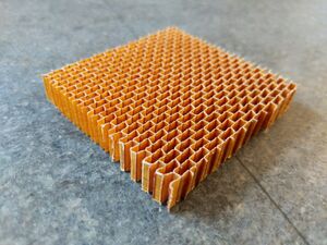
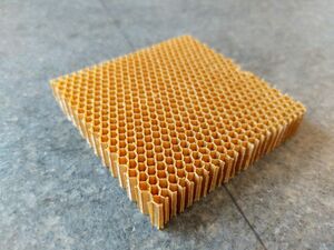
| Nomex honeycomb with hexagon cell | |
| Document Type | Article |
| Document Identifier | 326 |
| Relevant Class |
Material |
| Tags | |
Introduction[edit | edit source]
Honeycomb is an array of open cells made from thin sheets of material attached to each other. Honeycomb and composite sandwich panels can have extremely high performance and are commonly used in aerospace control surfaces, engine nacelles, interior shelving, floor panels and other light weight high stiffness applications. Honeycomb can be made from a wide range of metallic (aluminum, stainless steel) or nonmetallic (aramid (Nomex), polypropylene, polycarbonate, thermoplastic etc.) materials. Other applications of honeycomb include fluid smoothing (aerodynamic), architecture, energy absorbing structures and EMI/RFI shielding.
Scope[edit | edit source]
This page focuses on honeycomb core material. Honeycomb convention/terminologies, manufacturing processes, various types and cell configurations are discussed. Major suppliers of honeycomb materials are included.
Significance[edit | edit source]
Compared to other core materials such as wood or foam, honeycomb is more mass efficient as it provides a better combination of mechanical properties and light weight. Honeycomb as a core material should be considered whenever there is a skin buckling problem. Honeycomb combined with composite laminate skins can provide extremely high strength/stiffness parts with low weight. Along with high fatigue resistance honeycomb sandwich structures are ideal for many aerospace applications.
Honeycomb terminology[edit | edit source]
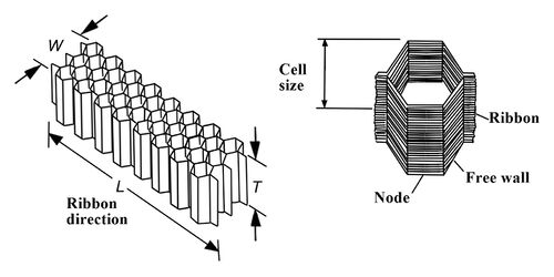
Some common terminology for honeycomb is listed below (please refer to the image). These conventions are often used during honeycomb and sandwich panel design and manufacturing:
- Honeycomb density - typically in pounds per cubic foot (pcf) or kilogram per cubic meter (kg/m3)
- Cell - a constituent unit of the honeycomb, honeycomb cells can have different configurations
- Ribbon - the flat(continuous) sheet material of the honeycomb, also known as web
- Node - the bonded portion of two adjacent ribbons
- Free wall - the unbonded portion of a cell
- Cell size - dimension between two nodes after expansion. (See honeycomb manufacturing process for details about expansion)
- L direction - the ribbon direction
- W direction - the direction in which the core is expanded, perpendicular to the L direction
- T direction - the direction parallel with the cell openings
Honeycomb manufacturing process[edit | edit source]
95% of honeycomb is made using adhesive bonding where lines of adhesive are printed at the nodes on the sheet material and stacked together. Other manufacturing methods include resistance welding, brazing, diffusion bonding, and thermal fusion; which are more expensive and used only for honeycombs that are seeing extreme conditions. For example, stainless steel and Inconel honeycomb have their nodes brazed or spot welded, and can be used up to around 700 °C (1300 °F). For some thermoplastic materials, the nodes are partially melted by heat, pressed together and solidify when cooled, no adhesives are required.[1]
There are two techniques for forming honeycombs from sheet materials: the expansion process and the corrugation process.
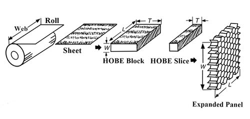
In the expansion process, flat sheets are stacked with adhesive printed in-between, forming the unexpanded block (honeycomb before expansion, HOBE). The adhesive is cured at elevated temperature and pressure (about 300 psi) in a press. Then the HOBE is cut to the desired thickness and expanded. When a metallic honeycomb is made by the expansion process, the sheet deform plastically at the nodes and maintaining the expanded geometry. When a non-metallic honeycomb material (such as paper, Nomex for example) is expanded, the honeycomb does not retain its shape and a rack is used to hold the honeycomb. The honeycomb is then dipped in liquid resin and cured in an oven to lock in the shape. The liquid resin is typically phenolic or polyimide and the dipping process is repeated (anywhere from 2 to 30 times) until the desired honeycomb density is reached.
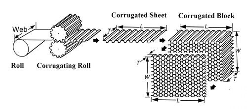
In the corrugation process, the flat sheets first pass trough a series of corrugating rollers, then the corrugated sheets are bonded at the nodes with adhesive and cured in an oven. This process is more applicable to core materials that can sustain its shape in corrugated sheet from (e.g. metals and some non-metallic materials, not paper). Since corrugated sheets are being stacked, only light pressure can be applied during the bonding and curing process. This results in much thicker adhesives (10% of total honeycomb weight) compared to the expansion process (around 1% of total honeycomb weight).[1]
Honeycomb cell configuration[edit | edit source]
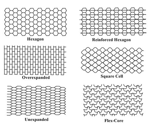
Different cell shapes/configurations require variation in the manufacturing process and can affect the mechanical properties and handling characteristics of the honeycomb. The most common cell shapes are hexagon, square and flex-core. Different configurations include overexpanded, underexpanded or reinforced.
The hexagon honeycomb cell resembles the natural bee hive and is the most common cell shape. The over-expanded core is the standard hexagon core but overexpanded, resulting in rectangular cell shape. The overexpanded core has lower bending stiffness in the L direction compared to the standard hexagon cell, making it easier to conform to curvatures in the L direction. The shear strength and modulus in the L direction is lower than in the W direction, which is higher compared to standard hexagon cell shape.
Metallic honeycomb[edit | edit source]
The most common metallic honeycomb materials are aluminum, stainless steel and titanium. Stainless steel is very commonly produced using the corrugation process. Copper and lead has also been made into honeycomb although much less common. The density of the metallic honeycomb core is mainly affected by foil thickness and cell configuration.
Aluminum honeycombs can be made by both expansion and corrugation. Corrugated aluminum cores are usually more expensive because it is more time consuming to produce. The corrugation method is used because it is impossible to expand the HOBE above 12 pcf (192 kg/m3). Corrugated aluminum cores density can range from 12 to 55 pcf (192-880 kg/m3) As a rule of thumb, expanded cores should be used whenever possible.[1]
Non-metallic Honeycomb[edit | edit source]
Once expanded, non-metallic cores are dipped in resin to fix the geometry[2]. Various thermoset and thermoplastic resins can be used depending on the application. Phenolic resin is very commonly used. Polyimide is used for high temperature applications. Thermoplastic can be used for increasing toughness. Typical resin content by weight is around 40% to 60%.
Fabric honeycombs can have the fabric oriented in 0°-90° direction (straight weave) or in ±45° direction (bias weave). The shear moduli of bias weave honeycomb can be three times higher than that of the straight weave honeycomb. For example, bias weave honeycomb made from carbon fiber (very costly) can be made into sandwich structures with extremely high stiffness and shear properties for some space applications. Because the constituent material is woven fabrics instead of sheets, fabric honeycombs require a different corrugation process to manufacture.
Thermoplastic honeycombs can be made by expansion, corrugation or extrusion. In either expansion or corrugation, the nodes are heat fused together, eliminating the use of adhesives. Whereas with extrusion, the honeycomb is extruded and sliced to the desired thickness. Thermoplastic honeycombs can be very tough but generally have lower strength compared to the thermoset counterparts.
Suppliers[edit | edit source]
Some major manufacturers and distributors of honeycomb include:
- Toray
- Hexel
- Dupont
- Corex honeycomb
- HoneyCommCore, LLC.
- Plascore
- The Gill corporation
- RAYPLEX
- MachineTek LLC
- Rock West Composites
Related pages
| Page type | Links |
|---|---|
| Introduction to Composites Articles | |
| Foundational Knowledge Articles | |
| Foundational Knowledge Method Documents | |
| Foundational Knowledge Worked Examples | |
| Systems Knowledge Articles | |
| Systems Knowledge Method Documents | |
| Systems Knowledge Worked Examples | |
| Systems Catalogue Articles | |
| Systems Catalogue Objects – Material | |
| Systems Catalogue Objects – Shape | |
| Systems Catalogue Objects – Tooling and consumables | |
| Systems Catalogue Objects – Equipment | |
| Practice Documents | |
| Case Studies | |
| Perspectives Articles |
References
- ↑ 1.0 1.1 1.2 [Ref] Bitzer, Tom (1997). Honeycomb Technology Materials, Design, Manufacturing, Applications and Testing. 1997 Springer Science+Business Media Dordrecht. doi:10.1007/978-94-011-5856-5. ISBN 978-94-011-5856-5.CS1 maint: uses authors parameter (link) CS1 maint: date and year (link)
- ↑ [Ref] Campbell, F.C. (2004). Manufacturing Processes for Advanced Composites. Elsevier. doi:10.1016/B978-1-85617-415-2.X5000-X. ISBN 9781856174152.CS1 maint: uses authors parameter (link) CS1 maint: date and year (link)
| About | Help |
Welcome
Welcome to the CKN Knowledge in Practice Centre (KPC). The KPC is a resource for learning and applying scientific knowledge to the practice of composites manufacturing. As you navigate around the KPC, refer back to the information on this right-hand pane as a resource for understanding the intricacies of composites processing and why the KPC is laid out in the way that it is. The following video explains the KPC approach:
Understanding Composites Processing
The Knowledge in Practice Centre (KPC) is centered around a structured method of thinking about composite material manufacturing. From the top down, the heirarchy consists of:
- The factory
- Factory cells and/or the factory layout
- Process steps (embodied in the factory process flow) consisting of:
The way that the material, shape, tooling & consumables and equipment (abbreviated as MSTE) interact with each other during a process step is critical to the outcome of the manufacturing step, and ultimately critical to the quality of the finished part. The interactions between MSTE during a process step can be numerous and complex, but the Knowledge in Practice Centre aims to make you aware of these interactions, understand how one parameter affects another, and understand how to analyze the problem using a systems based approach. Using this approach, the factory can then be developed with a complete understanding and control of all interactions.
Interrelationship of Function, Shape, Material & Process
Design for manufacturing is critical to ensuring the producibility of a part. Trouble arises when it is considered too late or not at all in the design process. Conversely, process design (controlling the interactions between shape, material, tooling & consumables and equipment to achieve a desired outcome) must always consider the shape and material of the part. Ashby has developed and popularized the approach linking design (function) to the choice of material and shape, which influence the process selected and vice versa, as shown below:
Within the Knowledge in Practice Centre the same methodology is applied but the process is more fully defined by also explicitly calling out the equipment and tooling & consumables. Note that in common usage, a process which consists of many steps can be arbitrarily defined by just one step, e.g. "spray-up". Though convenient, this can be misleading.
Workflows
The KPC's Practice and Case Study volumes consist of three types of workflows:
- Development - Analyzing the interactions between MSTE in the process steps to make decisions on processing parameters and understanding how the process steps and factory cells fit within the factory.
- Troubleshooting - Guiding you to possible causes of processing issues affecting either cost, rate or quality and directing you to the most appropriate development workflow to improve the process
- Optimization - An expansion on the development workflows where a larger number of options are considered to achieve the best mixture of cost, rate & quality for your application.
To use this website, you must agree to our Terms and Conditions and Privacy Policy.
By clicking "I Accept" below, you confirm that you have read, understood, and accepted our Terms and Conditions and Privacy Policy.

