Thermomechanical Analyzer (TMA) - A353
| Thermomechanical Analyzer (TMA) | |
|---|---|

| |
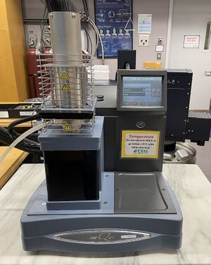
| Thermomechanical Analyzer, TA Instruments, Q400 | |
| Document Type | Article |
| Document Identifier | 353 |
| Themes | |
| Relevant Class |
Equipment |
| Tags | |
| Factory Cells | |
Introduction[edit | edit source]
Thermomechanical analysis (TMA) involves monitoring the changes in dimension of a sample as the temperature is changed. It is commonly used to determine the coefficient of thermal expansion (CTE) and glass transition temperature (Tg) of a material. The dimension of the sample is monitored and presented as a function of time or temperature at atmospheric pressure[1].
Features[edit | edit source]
A TMA instrument can typically heat samples up to 1000°C and cool to -150°C depending on the make and model. The sensitivity of the instrument is typically in the nanometer scale, for example, TA instruments TMA 450 has a sensitivity of 15 nm[2].
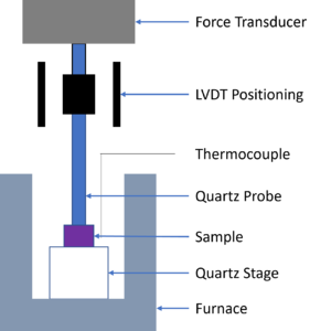
There are a variety of TMA instrument providers and models available on the market, but they all follow the same basic construction. A sample is placed on a stage inside of a moveable furnace, with a probe touching the sample. The probe is connected to a force transducer, usually some form of linear motor, with an LVDT position transformer to monitor the change in position of the probe as the sample expands/contracts. For position monitoring, optical and mechanical transducers are sometimes also used rather than an LVDT. The probe and the stage touching the sample are made from quartz due to its extremely low coefficient of thermal expansion and low thermal conductivity to separate the position monitoring form the instrument. The instrument is calibrated for the thermal expansion of the quartz. A thermocouple in close proximity to the sample is used to monitor the temperature[1].
The inside of the furnace is purged with a gas flowing in laminar flow to prevent turbulence in the air during temperature changes. The gas is also used to prevent degradation products from settling in the furnace, inert gas is used to prevent oxidation and the flowing gas increases the heat transfer into the sample. For high heat transfer into the sample helium is often used instead of nitrogen because of the relatively high thermal conductivity of the gas.
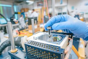
There are various fixtures that can be used in a TMA to support different sample geometries. A common sample is a cube of roughly 10x10x10mm, the cube will sit on a quartz stage with a probe on top of it applying a very small load (0.05N). There are also tension fixtures for thin films that grip the sample and apply a small tensile load. Lastly, there are submersion fixtures for testing the volumetric expansion of samples.
Uses and Test Types[edit | edit source]
The primary use of a TMA is to determine the coefficient of linear thermal expansion (CTE or CLTE). A TMA will output a plot of temperature vs dimension change, the linear region of these plots can be used to determine the CTE in that temperature range. The CTE, α, is the slope of \(\frac{\Delta L}{\Delta T}\) relative to the initial length of the sample \(L_0\)[3].
\[\alpha=\frac{1}{L_0}\left(\frac{\Delta L}{\Delta T}\right)\]
For composites it is important to keep in mind that the linear thermal expansion may be different in the x, y and z direction depending on the fibre orientation.
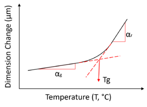
Another common use for a TMA is to determine the Tg of a polymer. The Tg is defined as the temperature where the free volume increases and there is a change in the rate of dimension change in the sample. A polymer that is above the Tg has much more degrees of freedom in the molecular chains and the CTE is higher and similar to that of a liquid[4]. To read more about Tg, see Glass transition temperature (Tg).
Some other properties that can be determined by the TMA are[1]:
- Creep – The TMA is capable of applying a constant stress on a sample and by monitoring temperature and deformation over time, a creep compliance can be determined.
- Stress relaxation – Applying a constant strain and monitoring the stress will allow the stress relaxation modulus to be established.
- Young’s modulus – The slope of the stress-strain curve can be determined for small strains and stresses on a material.
- Softening point and heat deflection temperature – using a penetration probe, these temperatures are determined by when the probe sinks a certain amount into the sample.
- Hard-core volume/incompressible volume – The volume at 0K can be extrapolated by using free-volume calculations.
Analysis of Results[edit | edit source]
See figure for idealized results of a simple TMA test. There are two CTEs indicated, \(\alpha_g\)and \(\alpha_r\), g representing the glassy state CTE and r for the rubbery state. Where the slope will be used to determine the two different CTEs. As well as a Tg, determined by the intersection of the extrapolated linear regions. This shows the change in the material form where the molecular chains have more freedom to move in the rubbery state and thus increasing the size of the sample much more rapidly.
Related pages
| Page type | Links |
|---|---|
| Introduction to Composites Articles | |
| Foundational Knowledge Articles | |
| Foundational Knowledge Method Documents | |
| Foundational Knowledge Worked Examples | |
| Systems Knowledge Articles | |
| Systems Knowledge Method Documents | |
| Systems Knowledge Worked Examples | |
| Systems Catalogue Articles | |
| Systems Catalogue Objects – Material | |
| Systems Catalogue Objects – Shape | |
| Systems Catalogue Objects – Tooling and consumables | |
| Systems Catalogue Objects – Equipment | |
| Practice Documents | |
| Case Studies | |
| Perspectives Articles |
References
- ↑ 1.0 1.1 1.2 [Ref] Menczel, Joseph D.; Prime, R. Bruce (2009). Thermal Analysis of Polymers: Fundamentals and Applications. John Wiley & Sons, Inc.CS1 maint: uses authors parameter (link) CS1 maint: date and year (link)
- ↑ [Ref] TA Instruments (2021). Discovery TMA Brochure (PDF) (Report). Retrieved 23 October 2023.CS1 maint: uses authors parameter (link)
- ↑ [Ref] Cassel, Bruce; Menard, Kevin (2013). Coefficient of Thermal Expansion Measurement using the TMA 4000 (PDF) (Report). Retrieved 23 October 2023.CS1 maint: uses authors parameter (link)
- ↑ [Ref] Menard, Kevin; Cassel, Bruce (2013). Basics of Thermomechanical Analysis with TMA 4000 (PDF) (Report). Retrieved 23 October 2023.CS1 maint: uses authors parameter (link)
| About | Help |
Welcome
Welcome to the CKN Knowledge in Practice Centre (KPC). The KPC is a resource for learning and applying scientific knowledge to the practice of composites manufacturing. As you navigate around the KPC, refer back to the information on this right-hand pane as a resource for understanding the intricacies of composites processing and why the KPC is laid out in the way that it is. The following video explains the KPC approach:
Understanding Composites Processing
The Knowledge in Practice Centre (KPC) is centered around a structured method of thinking about composite material manufacturing. From the top down, the heirarchy consists of:
- The factory
- Factory cells and/or the factory layout
- Process steps (embodied in the factory process flow) consisting of:
The way that the material, shape, tooling & consumables and equipment (abbreviated as MSTE) interact with each other during a process step is critical to the outcome of the manufacturing step, and ultimately critical to the quality of the finished part. The interactions between MSTE during a process step can be numerous and complex, but the Knowledge in Practice Centre aims to make you aware of these interactions, understand how one parameter affects another, and understand how to analyze the problem using a systems based approach. Using this approach, the factory can then be developed with a complete understanding and control of all interactions.
Interrelationship of Function, Shape, Material & Process
Design for manufacturing is critical to ensuring the producibility of a part. Trouble arises when it is considered too late or not at all in the design process. Conversely, process design (controlling the interactions between shape, material, tooling & consumables and equipment to achieve a desired outcome) must always consider the shape and material of the part. Ashby has developed and popularized the approach linking design (function) to the choice of material and shape, which influence the process selected and vice versa, as shown below:
Within the Knowledge in Practice Centre the same methodology is applied but the process is more fully defined by also explicitly calling out the equipment and tooling & consumables. Note that in common usage, a process which consists of many steps can be arbitrarily defined by just one step, e.g. "spray-up". Though convenient, this can be misleading.
Workflows
The KPC's Practice and Case Study volumes consist of three types of workflows:
- Development - Analyzing the interactions between MSTE in the process steps to make decisions on processing parameters and understanding how the process steps and factory cells fit within the factory.
- Troubleshooting - Guiding you to possible causes of processing issues affecting either cost, rate or quality and directing you to the most appropriate development workflow to improve the process
- Optimization - An expansion on the development workflows where a larger number of options are considered to achieve the best mixture of cost, rate & quality for your application.
To use this website, you must agree to our Terms and Conditions and Privacy Policy.
By clicking "I Accept" below, you confirm that you have read, understood, and accepted our Terms and Conditions and Privacy Policy.


