Effect of tooling in a thermal management system - A142
| Effect of tooling in a thermal management system | |
|---|---|
| Systems knowledge article | |
| Document Type | Article |
| Document Identifier | 142 |
| Themes | |
| Relevant Classes |
|
| Tags | |
| Prerequisites | |
Introduction[edit | edit source]
In processing of composites, the tooling and consumables constitute at least one boundary with respect to the part. In order for heat to transfer to and from the part, it must pass through the tooling/consumables. Hence, the parameters of the tooling can significantly impact the thermal response of the part. This includes the initial temperature of the tooling, which in turn impacts the initial part temperature. Since the system response is time-dependent, if the initial temperature of the tool-part assembly is not as expected, then its thermal response will similarly be unexpected.
Scope[edit | edit source]
This article discusses the impact tooling has on the part thermal response. The effect of various tooling parameters are investigated from a thermal management perspective. The page links out to foundational knowledge content and brings in physics-based simulation to demonstrate the impact of tooling in a thermal system. While the content presented here is applicable to all thermal management factory cells, the focus of this page is on the thermal transformation cell as that is the predominant cell associated with thermal management.
Significance[edit | edit source]
Tools are typically designed to support and provide shape to the part following well-defined mechanical requirements. However, it is also important that manufacturers consider thermal management specifications for tools. While the material(s), part(s), and even equipment parameters may be constrained, the tooling parameters are often not specified. Therefore, there is room to tailor the parameters of the tooling and consumables in order to achieve the necessary part thermal history. Small changes to the tooling may provide significant changes to the thermal response of the system. This, in turn, can affect the part temperature, gel time, and its final degree of cure (DOC).
Prerequisites[edit | edit source]
Recommended documents to review before, or in parallel, with this document:
- Degree of cure
- Heat of reaction
- Heat transfer
- Specific heat capacity
- Thermal conductivity
- Thermal diffusivity
- Thermal management
- System interactions
- Tooling and consumables (system class)
Analysis[edit | edit source]
There are a number of tooling parameters that may affect the outcome of the part in a thermal management system. The most significant are the tooling material, thickness, and initial temperature. However, the configuration of the tool should also be considered. Whether or not the tool has a substructure is important for the tool-side heat transfer coefficient (HTC), and the shape of the tool will influence airflow and local HTC values[1].

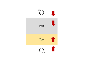
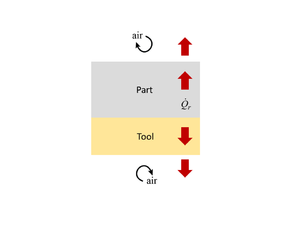
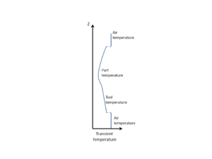
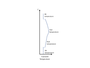
In regards to thermal management, the tool can be generalized as affecting the system in two ways; either behaving as a heat source, or a heat sink with respect to the part. The former occurs during a heat up scenario, in which heat must flow through the tool into the part. Initially, the tool and part are at the same temperature. Typically, as heat is added to the system, the tool heats up first which in turn transfers heat to the part, thus acting as a heat source. Both tool and part add thermal resistance to the system which results in a discrepancy between the part temperature and the applied temperature, known as thermal lag. In some cases, the tool may be the component applying heat to the system, in which case the tool still acts as a heat source, but the initial temperature of the part and tool are not the same. The second effect of tooling occurs during polymerization of the resin, when the material "exotherms". Here, additional heat is added to the system from the part. The part temperature is now greater than the tool temperature, meaning heat must escape through the tool. The tool behaves as a heat sink. In both cases, the tool acts as a medium of heat transfer. In the first case, the goal is to transfer heat to the part, whereas in the latter case the goal is to transfer heat away from the part. For a room temperature process, only the latter case need be considered, since there is no "heat up" stage. Conversely, both cases must be considered when processing at elevated temperatures.
In many cases, a 1D representation of the heat flow is adequate. Typically, the in-plane dimensions of composite materials are much larger than the their thickness. As a result, in-plane heat transfer can be ignored for most cases. This is a conservative approximation and does not always hold true. For example, highly conductive tooling materials (such as aluminum) may affect the validity of a 1D approximation. That said, the examples provided here are based on a 1D assessment.
| Heat-up | Exotherm |
|---|---|
Heat transfer into and out of the part occurs by conduction through the tool-part assembly. It is at the interface between the equipment and tool, and equipment and part, where convection takes place (if in a convective heating system). Recall that the ET interaction serves as the boundary conditions for the part. If the temperature across the upper and lower tooling surface (or part surface if not surrounded by tooling/consumables) is known, then the temperature within the part can be approximated using the 1D form of the heat balance equation, as shown below.
\(\frac{\partial}{\partial t}(\rho C_pT)=\frac{\partial}{\partial z}\Bigl(k_{zz}\frac{\partial T}{\partial z}\Bigr)+\dot{Q}_{r}\) 1D form of the heat transfer equation, where:<br />\(t\) = time,<br />\(\rho\) = density,<br />\(C_p\) = specific heat capacity,<br />\(T\) = temperature,<br />\(z\) = through-thickness distance (z direction),<br />\(k_{zz}\) = thermal conductivity in z direction, and<br />\(\dot{Q}_{r}\) = rate of energy given off by material during exotherm.
Where,
\(\dot Q_r = \frac{d\alpha}{dt}(1-V_f)\rho_r H_R\) Internal heat generation during polymerization (exotherm), where:<br />\(\dot{Q}_{r}\) = rate of energy given off by material,<br />\(\alpha\) = degree of cure,<br />\(t\) = time,<br />\(V_f\) = fibre volume fraction,<br />\(\rho_r\) = resin density, and<br />\(H_R\) = heat of reaction of resin
In order to understand the surface temperature of the tooling, it must be accurately measured or the heat transfer coefficient (HTC) of the equipment must be known. This is often a source of uncertainty in composites process modelling. To perform a thermal assessment of a part/tool or measure the HTC refer to the following pages:
- How to perform an experimental thermal profile
- How to perform a numerical thermal profile
- How to experimentally determine the HTC
- How to back calculate the HTC using simulation
Effect of geometry[edit | edit source]
Tooling thickness[edit | edit source]
In a thermal system, the tooling may act as a heat source or sink with respect to the part. The more thermally massive the tool, the more energy (heat) is required to raise its temperature. Since the tool is adjacent to the part, this directly affects the part temperature. For room temperature cure applications, there is no external heat added to the system. Rather, it is the exothermic polymerization reaction of the thermosetting material that contributes heat to the system and advances cure. If the heat that is given off is not managed properly, the part may thermally degrade (i.e. burn). One way to manage the part temperature is to use the tool as a heat sink. As the part gives off heat, the tool will absorb it. Again, the more thermally massive the tool, the more heat it will absorb. In other words, a thicker tool will absorb more heat from the part than a thin tool. This can be observed in left image in the figure below. The temperature of the part and tool start at 20°C. As polymerization kicks off, the part gives off an enormous amount of heat. With nothing to absorb the heat, a 10mm glass-polyester laminate can experience temperatures in excess of 200°C. As tooling thickness is increased, however, the maximum temperature is greatly reduced. That is not to say that the exotherm should be completely reduced, as often material systems, especially those cured at room temperature, make use of this additional heat. Polyester resins for example are typically cured at room temperature and utilize the heat generated from their polymerization reaction to advance the cure. On that note, while increasing tooling thickness reduces the maximum part temperature, it increases the time at which the part remains at elevated temperature. Just as increasing tooling thickness delays the heat up response of the part, due to the tool absorbing more heat, it also delays the cool down response of the part, as now more heat must be given off. The "no tool" case, for example, heats up relatively fast above 200°C and then cools relatively quick as well. Conversely, with a 30mm tool, the part heats up much slower to below 50°C, but remains at an elevated temperature for much longer This may be beneficial in reaching an appropriate degree of cure, or detrimental if at too high a temperature for too long. Achieving the appropriate thermal history for polyesters often boils down to managing this exothermic heat. Altering tooling thickness to achieve the appropriate thermal response of the part is not only an effective thermal management strategy for room temperature cures but also for high temperature cures.
At elevated temperatures, a thicker tool will result in a greater thermal lag between the part and environmental temperature, since more energy is spent heating the larger tool. Note the patterns observed in the right image in the figure below. In this scenario a carbon epoxy laminate is placed on an aluminum tool with varying thickness. The laminate is exposed to air on its top surface. Both part and tool are subject to a heat transfer coefficient indicative of that in a convection oven (20 W/m2k)[2][3]. With no tool present, the part temperature follows the applied temperature relatively closely. Eventually the exothermic polymerization reaction of the epoxy adds additional heat to the system and the part experiences a significant overshoot above the environmental temperature. In contrast, a tool thickness of 30mm results in a much slower thermal response of the part, but completely mitigates the exothermic overshoot. Tooling thickness does not only affect the rate in which the part is heated, but also in drawing heat from the part. That is why at a tooling thickness of 30mm, the exothermic nature of the part is subsided, because the heat released from the part is drawn into the tool. While the temperature overshoot may not be desirable, combating the effect with a large tool results in a longer cure cycle, since the part takes longer to reach the intended temperature of 180°C. This is a common optimization problem faced by manufacturers; meeting the intended temperature specifications with the shortest possible cure cycle. Moreover, just as in the room temperature case, the time it take for the part to cool down is in increased for thicker tools. If the tool is not thick enough to reduce the exotherm below the max allowable temperature, then it may contribute to holding the part above the max temperature for an extending period of time; an undesirable effect.
In order for a material system to achieve a high degree of cure, a sufficient amount of energy (heat) must be put into advancing the polymerization reaction. This is why for the room temperature scenario, a higher degree of cure is associated with a higher maximum temperature, because more thermal energy is available to advance the cure. As the polymerization reaction progresses, if the temperature does not reach the minimum energy threshold to continue advancing the cure, then the degree of cure will stabilize. Therefore, a thinner tool which results in a higher maximum temperature, advances the degree of cure further and at a faster rate. That said, in the case of the high-temperature processing scenario, while the cure rate may be different, the final degree of cure tends to the same value despite the differences in maximum temperature. This is because, regardless of tooling thickness, the system will eventually stabilize at the intended hold temperature of 180°C, which is high enough to raise the DOC to the final value shown for that material system. Conversely, at room temperature processing, once the part temperature has peaked, it will decrease in temperature until it eventually stabilizes at 20°C again. While the part temperature may be high enough to advance cure during the exotherm, if that temperature is not maintained then the cure reaction will eventually stop progressing as the part cools. Recall also that, in many cases, the amount of energy needed to advance polymerization to high DOC levels becomes significant. This is why the high temperature carbon-epoxy does not ever achieve a DOC of 1 under the given conditions, no matter the tooling thickness.
While a thinner tool may result in a higher DOC or a faster cure cycle, one should be wary to make the assumption that thinner tools are therefore better. As shown in the part temperature graphs, the maximum temperature can be quite high and, in many cases, above that of the material's degradation temperature. Hence, while a high degree of cure is desired, tooling thickness should be carefully chosen so not to degrade the part in achieving this goal.
| Room temperature (20°C) | High temperature (3°C/min to 180°C) |
|---|---|
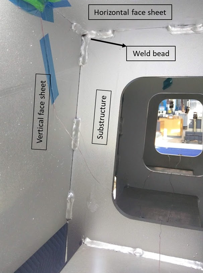
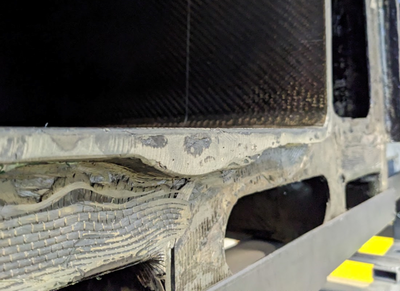
Tool surface thickness is not always consistent. One potential cause of this type of thickness variation is during tool construction, plates were welded and then machined to shape, see image below. As a result, thicker surfaces can lag thinner areas on the surface.
Tooling configuration[edit | edit source]
In forced convection heating (such as in an oven or autoclave), the configuration of the tool can significantly impact the airflow around the tool-part assembly[1]. This, in turn, affects the local heat transfer coefficient, altering the heat transfer to and from the part. Specifically, the shape and substructure of the tool are major factors.
Shape[edit | edit source]
Airflow impinging on the tool is affected by local obtrusions which may redirect the air and create localized dead zones with their own convection currents. Similarly, large cavities in the tool can also create dead zones of little to no airflow. All of this affects the HTC across the tool which in turn affects heat transfer to the part. While for simple geometry it may be reasonable to assume a global heat transfer coefficient across the tooling surface, the same assumption cannot be made if the geometry is complex. Local variations in HTC should be investigated. In fact, if a convective heating system, such as an oven or autoclave, is loaded with multiple parts and tools, the same effect may be observed. That is, the airflow impinging on one tool-part assembly may be redirected in such a way that it affects the airflow on subsequent tools/parts. To overcome this, the heating system must be able to maintain a constant airflow stream across each tool-part assembly. This can be especially challenging if the tool-parts being loaded are not consistent in geometry or in their position within the heating system. The latter point can be combated by always loading equivalent tools/parts in the same position for each run.
Refer to the following pages for measuring airflow:
Substructure[edit | edit source]
Tooling can generally be broken into two components. The facesheet (or skin), the upper section of tooling that supports and shape the part, and the substructure, the underside of the tool which provides support to the facesheet. The substructure can either be open or closed. Open, meaning air can easily flow through the underside of tool, versus closed where air cannot easily penetrate the underside of the tool. An example of open and closed substructures are shown.
An open substructure increases airflow under the tool, allowing for improved heat transfer and a higher HTC across the lower facesheet surface. A closed substructure, on the other hand, limits airflow, thus decreasing heat transfer and the HTC across the lower facesheet surface. For tools with a low thermal mass relative to the part, it is generally best to increase the toolside HTC. For tools with a high thermal mass relative to the part, the opposite is true, the toolside HTC should be decreased.
If the thermal mass of the tool is high relative to the part, increasing the toolside HTC may increase the maximum part temperature. This may seen counterintuitive. The reason is that the higher the thermal mass of the tool, the longer it takes to heat up. If the thermal mass is considerable, then when the part exotherms the tool will still be "cold", allowing for the tool to absorb a considerable amount of the exothermic heat generated. Increasing the toolside HTC, however, decreases the heat up time of the tool, thereby allowing for a higher tool temperature when the part exotherms. This reduces the energy absorbing capacity of the tool during exotherm, thus raising the part temperature. In contrast, tools with a low thermal mass compared to the part exhibit a similar temperature to the part at the time of exotherm. Moreover, owing to their low thermal mass, they cannot absorb as much thermal energy as high thermal mass tool. As a result, is is more important to draw heat away from the tool in this case. This is achieved by increasing the toolside HTC.
Refer to equipment effects in a thermal management system to learn more about HTC effects.
Localized weld beads (for metallic tools) or pad-ups (for composite tools) can also affect the thermal uniformity of the tool. Weld beads refers to areas where the substructure is welded to the tool surface. Pad-ups are commonly used to meet tooling thickness, vacuum specifications and sometimes to accommodate inserts, location holes etc. These extra mass takes more energy and time to heat up and can lag areas on the tool without these features.
Effect of material[edit | edit source]
Thermal mass is the mass of an object multiplied by its specific heat capacity. Mass can be further represented by an object's volume multiplied by its density. Therefore thermal mass is both dependent on geometry (volume) and material properties (density and specific heat capacity). In the above section, increasing tooling thickness is shown as one way to increase a tool's thermal mass. Another is to change the tooling material to a more dense and/or higher specific heat capacity material. From a thermal management perspective, doing this serves the same purpose as increasing the tooling thickness. It will raise the tool's thermal mass and allow it to better act as a heat sink. If the process requires the tool to absorb a considerable amount of heat, this may be a good choice. However, if the process requires that the tool and/or part is highly responsive to changes in temperature, this may be a poor choice.
\(Q=mC_p\Delta{T}\) Energy required to raise an object's temperature, where:<br />\(Q\) = energy,<br />\(m\) = object mass,<br />\(C_p\) = specific heat capacity, and<br />\(\Delta{T}\) = change in temperature from applied energy<br /><br />Note that \(mC_p\) is the thermal mass of the object.
\(\alpha=\frac{k}{\rho C_p}\) Thermal diffusivity, where:<br />\(\alpha\) = thermal diffusivity,<br />\(k\) = thermal conductivity,<br />\(\rho\) = density, and<br />\(C_p\) = specific heat capacity
Thermal mass is not the only factor that must be considered however. The tool's thermal conductivity and diffusivity play an important role. Thermal conductivity refers to how well the material transfers heat energy, while thermal diffusivity is a measure of the rate of this heat transfer, taking into account the object's conductivity and thermal mass. Thermal diffusivity is proportional to the thermal conductivity and inversely proportional to the specific heat capacity and density (related to thermal mass). In order for the tool to be an effective heat sink, it should have a high thermal conductivity. In that sense, it can easily draw heat from the environment and transfer it to the part, and vice versa. If the tool has both high thermal conductivity and is thermally massive, then it can not only readily transfer heat, but can also absorb a significant amount. If the thermal diffusivity of the material is also high, then heat can more easily dissipate through the material. What this means is that tools with high thermal diffusivities, such as aluminum, show more uniform temperature distributions. Tools with low thermal diffusivity tend to show more severe temperature gradients across their surface. Composite tools for example, have a generally low thermal diffusivity and also a low thermal mass. Therefore, they are subject to local temperature swings and may present significant difference in temperature across their surface. Their low thermal mass allows for them to heat up easily, but their low diffusivity does not allow for this heat to dissipate. On the other hand, while the diffusivity of invar and steel tools is still low compared to aluminum, it is much greater than that of most composite tools, and so too is their thermal mass. This means they take considerable energy to heat up but can dissipate that heat better than could a composite tool.
To see a practical example of these effects, refer to the tooling survey section below, which links out to a case study that demonstrates such phenomena. Quantitative values of physical and thermal material properties for tooling materials are provided in the table below, followed by a qualitative comparison of tooling materials.
| Tooling material | Density (kg/m3) | Specific heat capacity (J/kg-K) | Thermal conductivity (W/m-K) | Coefficient of thermal expansion - CTE (x10-6/°C) | Thermal diffusivity (x10-6m2/s) |
|---|---|---|---|---|---|
| Invar | 8000 | 515 | 11.0 | 0.6-1.5 | 2.67 |
| Mild steel | 7850 | 510 | 55 | 11 | 13.7 |
| Carbon-epoxy composite | 1580 | 870 | 0.7 (through-thickness) | -0.5 (in-plane) 22.5 (through-thickness) |
0.5 (through-thickness) |
| Aluminum | 2710 | 896 | 167 | 23 | 68.9 |
| Tooling material | Cost | Durability | Weight | Thermal mass | Thermal conductivity | Coefficient of thermal expansion (CTE) | Thermal diffusivity |
|---|---|---|---|---|---|---|---|
| Invar | $$$ | Excellent | Heavy | High | Moderate | Low | Low |
| Steels | $$$ | Excellent | Heavy | High | Good | Moderate | Moderate |
| Composites | $ | Low | Light | Low | Low | Moderate | Low |
| Aluminum | $$ | Good | Moderate | Low | Excellent | High | High |
In the above figures (from the previous section), aluminum was used, which has a high thermal conductivity and high thermal diffusivity, but less thermally massive than steel or invar. Metals in general are good thermal conductors, therefore in the examples shown below, the increase in thermal mass associated with steel and invar tools translates to them being more effective heat sinks for part. In general, however, a composite tool is thermally light and has a lower thermal conductivity than the metals shown. Hence, the thermal response of the part is more exaggerated for a composite tool.
At room temperature, changing the material of the tool can significantly impact the part temperature during exotherm. With the glass-polyester system shown (left image below), changing from a 10mm composite tool to a 10mm invar tool reduces the maximum part temperature by 70°C. Although not as drastic, a similar response is seen at high temperature for a carbon-epoxy system (right image below). A 10mm composite tool results in a notable exotherm, 20°C above the environmental conditions. A 10mm steel and invar tool, on the other hand, reduce the part temperature overshoot to less than 10°C above the applied temperature.
Just as with thickness effects, a higher maximum temperature associated with a given tooling material results in a higher degree of cure for room temperature processing. Again, during high-temperature processing, however, the part eventually reaches the intended temperature regardless of the tool material. Therefore, the final degree of cure for each tooling material is the same; it is only the time in reaching the final DOC that differs. For both room and high-temperature processing, caution should be taken to avoid raising the part temperature above the material's degradation temperature.
| Room temperature (20°C) | High temperature (3°C/min to 180°C) |
|---|---|
The tool does not need to contain a single material (or thickness). In fact, realizing the use of the tool from a thermal perspective allows one to tailor its design to achieve the necessary properties. For example the tool assembly could comprise a thermally massive facesheet of invar (or steel), supported by a highly conductive block of aluminum to act as a heat sink. During heat up, the aluminum will readily conduct heat into the invar facesheet supporting the part. Similarly, during exotherm, the aluminum block will transfer heat away from the invar facesheet, thereby reducing excess heat given off by the part.
Fibre content (composite tool)[edit | edit source]
The thermal properties of composite tools are largely dependent on the volume fraction of fibre and resin, since the fibres and resin have different thermal properties. In the case of carbon fibre epoxies, the fibres are significantly better thermal conductors than the epoxy, while the specific heat capacity and density are fairly similar. Therefore the varying thermal response of CFRP tools is largely due to differences in thermal conductivity arising from their fibre volume fraction. A composite tool with a high fibre volume fraction will conduct heat much more readily than an equivalent tool with a low fibre volume fraction.
The anisotropic nature of composites also influences the thermal properties of composite tools, as they will have different properties depending on the fibre direction.
While metallic tools may be more rugged and can handle high temperature applications, composite tools are more sensitive. Aside from thermally degrading the composite part, it is also possible to thermally degrade a composite tool. As such, it is important that the tool also does not exceed its maximum temperature specifications.
Tooling survey[edit | edit source]
Understanding how the tooling parameters influence the thermal response of the part is important when designing and selecting tools. In addition to understanding the general effects that tooling may play, one can conduct a tooling survey to understand the specific thermal response of their individual tools. This means running tools through thermal cycles without the part present and measuring the temperature of the tool. This allows manufacturers to ascertain a better idea of how their tooling will behave during a production run. Of course, the thermal resistance and exothermic heat of the part is not captured in such a study. However, as explained in this page, the thermal response of the part is heavily influenced by the thermal response of the tool. Therefore, understanding how the tool behaves without the part is useful in understanding how the part will behave when placed on the tool.
The following link provides an example of a thermal tooling survey conducted on three complex tools having the same geometry but constructed of different materials. The results from this study demonstrate the applicability of the information presented in this page.
Scenarios[edit | edit source]
1. A boat manufacturer is performing a room-temperature wet layup with a glass-polyester composite. The technical data sheet for the resin says the maximum processing temperature for the resin is 100°C. They are considering an aluminum or composite tool and wish to know what tooling thickness/material they should use to achieve the temperature specification while obtaining the highest DOC. As well, they would like to know the resulting gelation time.
In order to find the optimum tooling thickness to satisfy the temperature requirement, a thermal study must be performed on the tooling. It is assumed that the heat flow is one-dimensional. Using simulation software, the following curves are generated.
The figures show that under the given processing conditions the composite tool will never pass the temperature requirements. Therefore an aluminum tool is chosen. The minimum thickness needed to satisfy the temperature specification is ~12mm. The associated DOC for the 12mm aluminum tool is 0.96. However, for a small reduction in DOC, the manufacturer can select a 15mm tool which will bring the maximum part temperature down to 80°C. This will ensure that the part does not go above 100°C if unexpected, small temperature fluctuations occur. From the curves, a 15mm aluminum tool results in a DOC of ~0.94.
It is known that for this material system gelation occurs at a DOC of 0.1. Therefore gelation time can be deduced from a plot of DOC vs time for a 15mm aluminum tool
The gelation time of the resin in the system described above is approximately 116 minutes, or just under 2 hours, when cured at room temperature in stagnant air.
Complicating factors/edge cases[edit | edit source]
It should be noted that while this page demonstrates the general effects tooling has in a thermal system, the figures generated are material specific. Results will differ between materials, even for seemingly similar material systems (i.e. one polyester resin based system versus another). Similarly, changes in other processing parameters such as part thickness or HTC values will influence the outcomes. The results shown here are intended only to highlight the importance of tooling from a thermal management perspective. Finally, addition of consumables such as release film, breather, and vacuum bagging material were largely overlooked in the plots to simplify the explanation. Depending on the thermal properties and thickness of the consumables added, they may have a notable effect on the system. This is especially true for breather which can act as an insulator within a thermal system. The effect of consumables should be considered if a vacuum bag assembly is used.
Related pages
| Page type | Links |
|---|---|
| Introduction to Composites Articles | |
| Foundational Knowledge Articles | |
| Foundational Knowledge Method Documents | |
| Foundational Knowledge Worked Examples | |
| Systems Knowledge Articles | |
| Systems Knowledge Method Documents | |
| Systems Knowledge Worked Examples | |
| Systems Catalogue Articles | |
| Systems Catalogue Objects – Material | |
| Systems Catalogue Objects – Shape | |
| Systems Catalogue Objects – Tooling and consumables | |
| Systems Catalogue Objects – Equipment | |
| Practice Documents | |
| Case Studies | |
| Perspectives Articles |
References
- ↑ The curves presented on this page were generated using RAVEN software by Convergent Manufacturing Technologies. Other thermal simulation software exists and CKN is not endorsing use of RAVEN over other software packages.
References
- ↑ 1.0 1.1 [Ref] Fabris, Janna et al. (2018). "Effect of tool design on thermal management in composites processing" (PDF). Cite magazine requires
|magazine=(help)CS1 maint: extra punctuation (link) CS1 maint: uses authors parameter (link) - ↑ [Ref] Carson, James K. et al. (2006). "Measurements of heat transfer coefficients within convection ovens". 72 (3). doi:10.1016/j.jfoodeng.2004.12.010. ISSN 0260-8774. Cite journal requires
|journal=(help)CS1 maint: extra punctuation (link) CS1 maint: uses authors parameter (link) - ↑ [Ref] Balk, O. D. et al. (1999). "Heat transfer coefficients on cakes baked in a tunnel type industrial oven". 64 (4). doi:10.1111/j.1365-2621.1999.tb15111.x. ISSN 0022-1147. Cite journal requires
|journal=(help)CS1 maint: extra punctuation (link) CS1 maint: uses authors parameter (link) - ↑ [Ref] Empty citation (help)
| About | Help |
Welcome
Welcome to the CKN Knowledge in Practice Centre (KPC). The KPC is a resource for learning and applying scientific knowledge to the practice of composites manufacturing. As you navigate around the KPC, refer back to the information on this right-hand pane as a resource for understanding the intricacies of composites processing and why the KPC is laid out in the way that it is. The following video explains the KPC approach:
Understanding Composites Processing
The Knowledge in Practice Centre (KPC) is centered around a structured method of thinking about composite material manufacturing. From the top down, the heirarchy consists of:
- The factory
- Factory cells and/or the factory layout
- Process steps (embodied in the factory process flow) consisting of:
The way that the material, shape, tooling & consumables and equipment (abbreviated as MSTE) interact with each other during a process step is critical to the outcome of the manufacturing step, and ultimately critical to the quality of the finished part. The interactions between MSTE during a process step can be numerous and complex, but the Knowledge in Practice Centre aims to make you aware of these interactions, understand how one parameter affects another, and understand how to analyze the problem using a systems based approach. Using this approach, the factory can then be developed with a complete understanding and control of all interactions.
Interrelationship of Function, Shape, Material & Process
Design for manufacturing is critical to ensuring the producibility of a part. Trouble arises when it is considered too late or not at all in the design process. Conversely, process design (controlling the interactions between shape, material, tooling & consumables and equipment to achieve a desired outcome) must always consider the shape and material of the part. Ashby has developed and popularized the approach linking design (function) to the choice of material and shape, which influence the process selected and vice versa, as shown below:
Within the Knowledge in Practice Centre the same methodology is applied but the process is more fully defined by also explicitly calling out the equipment and tooling & consumables. Note that in common usage, a process which consists of many steps can be arbitrarily defined by just one step, e.g. "spray-up". Though convenient, this can be misleading.
Workflows
The KPC's Practice and Case Study volumes consist of three types of workflows:
- Development - Analyzing the interactions between MSTE in the process steps to make decisions on processing parameters and understanding how the process steps and factory cells fit within the factory.
- Troubleshooting - Guiding you to possible causes of processing issues affecting either cost, rate or quality and directing you to the most appropriate development workflow to improve the process
- Optimization - An expansion on the development workflows where a larger number of options are considered to achieve the best mixture of cost, rate & quality for your application.
To use this website, you must agree to our Terms and Conditions and Privacy Policy.
By clicking "I Accept" below, you confirm that you have read, understood, and accepted our Terms and Conditions and Privacy Policy.

