Case Study for Using Construction Foam as Tooling Material - C120
| Case Study for Using Construction Foam as Tooling Material | |||||||
|---|---|---|---|---|---|---|---|
| Case study | |||||||

| |||||||
| Document Type | Case study | ||||||
| Document Identifier | 120 | ||||||
| Objective functions |
| ||||||
| MSTE workflow | Development | ||||||
| Prerequisites | |||||||
Summary[edit | edit source]
The CRN was approached to assist in manufacturing a prototype as a proof of concept for a client, with the goal of creating low cost tooling capable of producing three to four parts. One of the selected approaches was to use insulation foam board, a rigid thermoplastic foam board commonly used in construction. The foam boards were bonded together and surface sealed before a Wet layup was performed. The demould was relatively challenging, however a successful part was produced. The tool sustained damage from demoulding and adhesive squeeze out from Vacuum Bagging.
Challenge[edit | edit source]
The client for this project required a proof of concept part at low cost to demonstrate the fit and visual appeal of the part. The challenge was twofold. First, design changes were anticipated, making it impractical to commit to an expensive tool. Secondly, this part was for the exterior of a helicopter, requiring a smooth airside surface for aerodynamic performance. For this concept part, this translated to achieving an A-class surface finish.
Approach[edit | edit source]
Construction foam (GreenGuard Type IV Insulation Board) was cut to size on a bandsaw and bonded to form a block using LePage PL300 Foam Board adhesive. The foam block had the shape of the part machined into it by the UBC Materials Department Machine Shop using a CNC milling machine. Once machining was done, gaps and defects in the foam were filled in using Bondo body filler. After the body filler was sanded smooth, the tool was split in half using the bandsaw. Afterwards, three layers of West System 105 resin and 206 slow hardener were added to the tool and sanded down smooth. Once the surfaces were smooth, a gasket was bonded on one side of the split using the same West System resin. Finally, the tool was assembled and ready for the wet layup.
Foam Block Manufacturing[edit | edit source]
CRN obtained multiple sheets of Kingspan Greenguard Insulation Foam that were over 91 cm x 91 cm [36” x 36”] with a thickness of 5 cm [2”]. The sheets of foam needed to be bonded together to create a foam block large enough to contain the shape of the part. Based on the CAD model, five sheets of foam were needed to fully house the cavity created by the part they were cut to size using a bandsaw (48 cm x 71 cm [19” x 28”]).
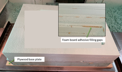
Initially, the foam boards had uneven surfaces, resulting in large voids in between the sheets of foam. Some processing of the foam boards was required to minimize this. The boards were sanded using 100 grit sandpaper and an orbital sander until the sheets were mostly flat, determined by eye using a straightedge. Sheets were then bonded with LePage PL300 Foam Board adhesive, applied and spread evenly.
The foam block was delivered to the UBC Materials Engineering Machine Shop for CNC milling of the cavity. The machinists attached a sheet of 1.75 cm [11/16”] thick plywood to bottom of the foam block using PL300 foam block adhesive as a base plate to mount the block in the CNC milling machine. The machinists mentioned that the PL300 adhesive would fill up the grooves in the cutting tool, hindering cutting and causing them to pause the machine to clean the cutting tool.
Surface Preparation[edit | edit source]
Once the CRN received the machined foam block from the UBC Materials Engineering Machine Shop, the next step in manufacturing the tooling was to use body filler to fill in gaps in the foam and add a sealing epoxy layer.
Two options for body filler were tested: 3M Bondo and Abatron WoodEpox. Bondo was selected to be the body filler as its cure time was significantly shorter than the WoodEpox. It was not obvious in the test samples but after applying the Bondo to the machined foam block, it was discovered that the foam is slightly dissolved or melted. This made it difficult to ensure the surface was uniform and required a significant amount of hand sanding. Once the Bondo was at a point where the surface finish was mostly smooth, the foam block was cut in half using the bandsaw across the width in order to make the tool a two part mould. Cutting the foam block in half at this point caused the remaining sanding of the sealer to create a bevel at the split, rounding over the otherwise sharp corner. This caused a slight misalignment between the two halves and created an uneven surface at the split. It would be best to complete sealing and sanding before splitting the tool.
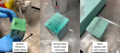
After splitting the foam tool, several resins and sealers were tested on the foam to ensure compatibility. Multiple sealing products were tested and would dissolve the foam as seen in the figure below. The West System 105 resin and 206 slow hardener system was selected due to its compatibility with the foam. After applying the first layer of the resin, the resin was sanded using 100 grit sand paper until it was smooth. Two more layers of resin were applied and sanded down smooth. Following the third layer, the resin was sanded using increasing grits of sandpaper:
- 100
- 320
- 800
- 1200
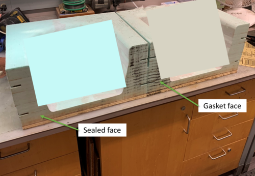
As seen in the figure below, one face of the split was sealed using the same West System Epoxy system while the other had a laser cut gasket adhered using the resin as well. Note: details of the part geometry are intentionally obscured in the figures.
Tool Assembly[edit | edit source]
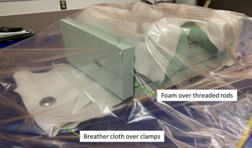
After completing surface preparation, the tool could be assembled in preparation for the layup. Four 0.635 cm [1/4"] threaded rods and a plate on either end of the tool were used to align the two parts of the tool. Although wing nuts and washers were used on the threaded rods to apply compression on the plates to seal the split, there was still a gap in the bottom of the tool. Two large clamps were used to apply more compression and try to seal the split better.
A vacuum bag sealed around the edge of the top face of the tool, was tried but was found to be leaking, likely through the split. Adding a layer of flashbreaker tape over the split to try and seal better did not stop the leak. In the end, a large envelope vacuum bag was used as this would provide better compaction than the leaky vacuum bag around the edge, see figure below. The tool is now ready for the layup.
Demould[edit | edit source]
After the part was cured at room temperature. Wedges were used to try and pry the part up and out of the cavity from the top face, but it appeared to be stuck near the split. This could be a nature of the split or an interaction with the flashbreaker tape. Having the plywood base plate was extremely helpful as the foam was too soft to pry against, but using the plywood, wedges could be inserted until the tool separated at the split. Once the tool was split, one half was easily removed and the other half was worked free after some pulling. However, the split left a groove on the part that will require some post-processing to remove.
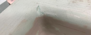
During the demould process, the foam was too soft to pry against and resulted in some damage to the sealing resin coat on the top surface. Some areas were cracked due to pressure exerted when prying the part up, see example in the figure below, while other areas saw the sealing resin coat peeled off due to interactions with the flashbreaker tape.
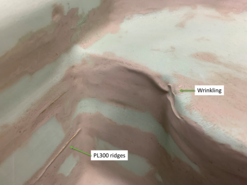
The foam exhibited peculiar behaviour after the completion of the layup. Some areas of the tool experienced wrinkling, forming ridges and wrinkles that can be seen in the part. Some of these ridges occur near the PL300 adhesive areas as show in the figure below. It is likely that these defects are caused by the exotherm of the cure, the pressure from the vacuum or both.
Outcome[edit | edit source]
Below is a summary of the strengths and flaws of using construction foam as a tooling material.
Strengths[edit | edit source]
There are a few strengths of using foam to manufacture a tool:
- Light weight
- Cost effective
- Ease of machining
- Minimal wear on CNC milling tools
- Easy to cut on bandsaw
Weaknesses[edit | edit source]
- Panels were wavy and needed to sand panels flat to bond together
- Panels needed to be bonded together to form a foam block
- Foam is soft
- Needed plywood base plate to be mounted in CNC milling machine
- Large dimensional tolerance due to sanding
- Foam saturates sand paper easily
- Chips and dents easily
- Too soft to pry against during demould
- Not compatible with some materials
- Dissolved or melted when using System Three S-1 sealer epoxy
- Dissolved or melted when using Aervoe Clear Acrylic clear coat spray
- Lightly dissolved or melted when using 3M Bondo
- Foam is porous
- Required many layers of Bondo
- Required many layers of epoxy to seal
Although the part was successfully manufactured and the material cost was low, there are a variety of drawbacks to using construction foam as tooling material. The low strength and incompatibility with resins added challenges to the manufacturing of the tool, this added a large cost in man hours for this process. The squeeze out of foam adhesive and damage to the tool during cure and demould also highlights how this type of tool is very likely to see very low cycles.
| About | Help |
Welcome
Welcome to the CKN Knowledge in Practice Centre (KPC). The KPC is a resource for learning and applying scientific knowledge to the practice of composites manufacturing. As you navigate around the KPC, refer back to the information on this right-hand pane as a resource for understanding the intricacies of composites processing and why the KPC is laid out in the way that it is. The following video explains the KPC approach:
Understanding Composites Processing
The Knowledge in Practice Centre (KPC) is centered around a structured method of thinking about composite material manufacturing. From the top down, the heirarchy consists of:
- The factory
- Factory cells and/or the factory layout
- Process steps (embodied in the factory process flow) consisting of:
The way that the material, shape, tooling & consumables and equipment (abbreviated as MSTE) interact with each other during a process step is critical to the outcome of the manufacturing step, and ultimately critical to the quality of the finished part. The interactions between MSTE during a process step can be numerous and complex, but the Knowledge in Practice Centre aims to make you aware of these interactions, understand how one parameter affects another, and understand how to analyze the problem using a systems based approach. Using this approach, the factory can then be developed with a complete understanding and control of all interactions.
Interrelationship of Function, Shape, Material & Process
Design for manufacturing is critical to ensuring the producibility of a part. Trouble arises when it is considered too late or not at all in the design process. Conversely, process design (controlling the interactions between shape, material, tooling & consumables and equipment to achieve a desired outcome) must always consider the shape and material of the part. Ashby has developed and popularized the approach linking design (function) to the choice of material and shape, which influence the process selected and vice versa, as shown below:
Within the Knowledge in Practice Centre the same methodology is applied but the process is more fully defined by also explicitly calling out the equipment and tooling & consumables. Note that in common usage, a process which consists of many steps can be arbitrarily defined by just one step, e.g. "spray-up". Though convenient, this can be misleading.
Workflows
The KPC's Practice and Case Study volumes consist of three types of workflows:
- Development - Analyzing the interactions between MSTE in the process steps to make decisions on processing parameters and understanding how the process steps and factory cells fit within the factory.
- Troubleshooting - Guiding you to possible causes of processing issues affecting either cost, rate or quality and directing you to the most appropriate development workflow to improve the process
- Optimization - An expansion on the development workflows where a larger number of options are considered to achieve the best mixture of cost, rate & quality for your application.
To use this website, you must agree to our Terms and Conditions and Privacy Policy.
By clicking "I Accept" below, you confirm that you have read, understood, and accepted our Terms and Conditions and Privacy Policy.

