Darcy's law - A362
| Darcy's law | |
|---|---|
| Document Type | Article |
| Document Identifier | 362 |
| Themes | |
| Relevant Class |
Material |
| Tags | |
| Prerequisites | |
Introduction[edit | edit source]
Darcy's Law is a fundamental principle used to model fluid flow through porous media, and it is important for understanding resin flow in composite materials. In composite manufacturing processes such as resin transfer molding (RTM), vacuum infusion, and compression molding, the resin must infiltrate the reinforcement fibers uniformly to achieve optimal fiber wetting and mechanical properties. Darcy's Law provides a framework for predicting how the resin moves through the porous reinforcement material, helping to ensure consistent resin distribution, minimize defects, and improve the overall quality of the composite part. The law is based on the relationship between pressure, viscosity, permeability, and flow rate, all playing a role in controlling resin flow in composite manufacturing.
Significance[edit | edit source]
Understanding and applying Darcy's Law to resin flow is essential for controlling the infusion process and ensuring adequate time is available for distribution of resin throughout the reinforcement. By quantifying the relationship between pressure gradients and flow velocity, Darcy's Law helps to predict how resin will move through the fibers and how changes in parameters like pressure, viscosity, or permeability may affect the flow behavior. This is particularly important for avoiding common issues such as incomplete fiber wetting, resin-rich areas, or dry spots, which can lead to reduced mechanical performance, increased weight, and the formation of defects like voids or porosity.
Significance[edit | edit source]
This page will review the key concepts behind Darcy's Law and its application in modeling resin flow during composite manufacturing
Background[edit | edit source]
Resin flow through composite reinforcements is commonly modelled using Darcy’s law, as shown in Equation (1). In this equation, the volumetric flow is established per second. Therefore each of the variables should be approximated for the flow travel over this time period at the flow front.
\(Q = -\frac{KA}{\mu}\frac{\Delta P}{x}\)
Where,
\(Q = \) Volumetric flow rate
\(K = \) Preform permeability
\(A = \) Preform cross-sectional area
\(\mu = \) Resin viscosity
\(\Delta P = \) Pressure differential across preform
\(x = \) In-plane flow distance of pressure differential
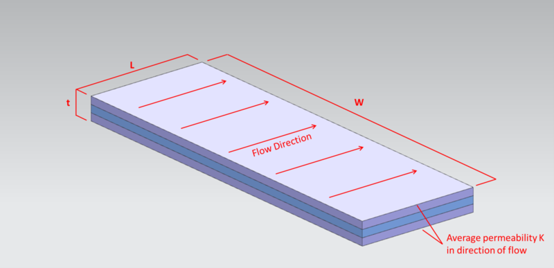
The figure below shows the flow through a typical laminate stack:
Different methods can be utilized to modify each of the terms in Darcy’s law to provide sufficient flow through a laminate. Common methods to be considered for each term are discussed in the following sections:
Permeability[edit | edit source]
Permeability refers to a material’s ability to transmit fluids through its structure. In the context of composite manufacturing, it describes how easily air and resin can flow through the layers of the reinforcement material. For simplicity, standard composite layups are often modeled with an average permeability across the entire cross-section, a methodology suited for macroscale flow modeling. his approach is effective when the permeability of the individual plies in the flow direction is relatively uniform.
The permeability of reinforcing materials is highly influenced by the fiber architecture. For example, unidirectional fibers typically have significantly higher permeability along the direction of the fibers compared to perpendicular directions. For woven materials, the tightness of the weave will influence the permeability of the mat. Reinforcements with a loose weave will have a higher permeability. Many of these considerations are required when attempting to model the flow at the mesoscale.
At the microscale, permeability refers to the fluid flow between individual fibers within a tow. This permeability is largely dependent on the type of reinforcing material. Different fibers have varying diameters and packing configurations within the tow, which directly affect the permeability. For instance, carbon fiber tows typically have lower permeability compared to glass fiber tows due to their smaller diameter and tighter fiber packing.
Permeability in Different Directions[edit | edit source]
The permeability of a reinforcement ply is generally one or two orders of magnitude higher in the in-plane directions (parallel to the surface) than in the through-thickness direction (perpendicular to the surface). Therefore the in-plane permeability is often the only consideration for thin laminates. For thicker laminates, the through-thickness direction must be considered as well. Similarly, when incorporating internal flow media, the flow may primarily be in the through-thickness directions when flowing through the plies. With the flow media, the low permeability of the plies in this direction is often offset by the very short infusion distance required and the large flow front surface area.
The permeability of a composite structure will also be affected by the required fibre volume for the part. Processes that have higher fibre volumes will have a much lower permeability. Light RTM processes typically have a lower fibre volume than other RTM processes which would result in a higher permeability. Additionally, Light RTM processes often incorporate flow media within the reinforcements, creating layers with higher permeability that facilitate resin flow.
Measuring permeability[edit | edit source]
Permeability is a critical factor in flow modeling, but no standardized test method exists to determine this property. Many test methods have been proposed, though all have shown a high degree of variability. Conducting the same test at different facilities can yield results that differ by an order of magnitude. Although refinements have been made to reduce variability, test results often show a standard deviation of ±20%. The experimental methods typically focus on measuring the in-plane permeability of reinforcement materials, with test fluids commonly consisting of oils like vegetable oils, corn syrups, or motor oils, which mimic the properties of composite resins.
The tests are commonly conducted using either a linear edge-to-edge flow or a centre-out flow type. Both test types offer their own advantages and disadvantages. The linear edge-to-edge flow method tends to offer better repeatability but requires a larger number of tests to determine the permeability of anisotropic materials. Visual measurement techniques are typically employed to track the flow of fluid through the reinforcement material over time.
Draping[edit | edit source]
The draping of reinforcement plies can significantly impact their permeability. Studies have shown that the permeability of a ply can change by more than 50% due to shear forces during draping. This variability is one of the challenges in accurately predicting resin flow and permeability, making experimental results and predictive modeling difficult to standardize.
Viscosity[edit | edit source]
Viscosity is a measure of a liquid's resistance to flow or deformation under a given rate of shear. Infusion resin suppliers will typically provide the viscosity of the resin in centipoise (cP) or provide information on the viscosity of the resin as it relates to temperature. This is important, as resin viscosity can change significantly based on processing conditions such as temperature, which in turn affects the flow rate and resin penetration into the reinforcement material.
When selecting a resin for infusion processes such as Vacuum Assisted Resin Transfer Molding (VARTM) or Light RTM, resin viscosity should be one of the primary factors considered. For these processes, ideal resin viscosities are typically around 100 cP, which offers a balance between manageable flow and adequate control. However, resins with viscosities up to 500 cP can still be used effectively, depending on the specific requirements of the process. The viscosity of the resin directly influences the time it takes to fill the mold. Higher viscosity resins flow more slowly, requiring longer infusion times to fully saturate the fiber preform. If a resin has a short gelation time or cure time, the infusion process may need to be completed quickly to avoid premature setting of the resin before the part is fully filled. One of the most significant challenges associated with high viscosity resins is the potential for incomplete filling of the mold. As viscosity increases, the resin’s ability to flow through the reinforcement fibers decreases. If the viscosity is too high, the resin may not adequately fill the entire cavity, leading to dry spots or voids in the composite, which can negatively impact the final product’s quality and mechanical properties.
Cross-Sectional Area[edit | edit source]
The cross-sectional area refers to the plane or surface that is perpendicular to the flow direction. The cross-sectional area has a direct correlation with the flow through the part cavity. While the cross-sectional area is typically governed by the geometry of the part, there are various methods that can be employed to manipulate this property for optimal flow management.
One of the most important factors to consider when designing an infusion system is the method of infusion. Different infusion techniques influence the cross-sectional area in various ways, which in turn affects the flow rate required to fill the mold.
- Center-out Infusion: In a center-out infusion method, the resin flows from a single point (the infusion port) in a circular pattern. Initially, the available cross-sectional area is relatively small, which can limit the flow of resin as it begins to move outward. However, as the flow front advances, the cross-sectional area increases, resulting in a higher total flow. This method requires careful management of resin flow to ensure that the increasing area does not lead to uneven resin distribution or delays in filling.
- Perimeter Infusion: When using a perimeter infusion method, the largest cross-sectional area is present at the start of the process, as the resin must fill the entire perimeter of the part. This results in the highest flow rate at the beginning of the infusion. As the resin flows towards the central vacuum port, the cross-sectional area decreases, leading to a reduction in the flow rate required. This method provides a predictable flow profile but requires careful control to ensure the resin does not gel or cure prematurely.
- Edge-to-edge Infusion: In edge-to-edge infusion, the cross-sectional area remains relatively consistent throughout the process, assuming the part itself has a uniform cross-section. This results in a more stable flow rate during the entire infusion process, provided that other factors, such as resin viscosity and pressure, are kept constant. This method is advantageous for ensuring uniform resin distribution across the entire part, particularly in complex or large parts with consistent geometry.
Length[edit | edit source]
The length refers to the distance the resin must travel along the flow direction to fully fill the part. A longer flow length increases the required flow rate within a given time period, as the resin has to cover a greater distance to complete the infusion.
There are several strategies that can be employed to optimize the total length required for an infusion, which can improve flow efficiency and reduce the overall infusion time:
- Multiple Infusion Ports: For large components, incorporating multiple infusion ports is often recommended. This approach helps to shorten the flow distance from each port, reducing the total length the resin needs to travel. By distributing the resin flow from several entry points, the process becomes more efficient, leading to more uniform resin distribution and reduced risk of uneven filling.
- Infusion Geometries: The geometry of the infusion system can also be adjusted to control the flow path. For example, using branching or strategic flow path designs can distribute the resin more evenly across the length of the part. This method ensures that the resin flows in multiple directions from the infusion points, effectively halving the required flow distance in each direction. The result is a more uniform and controlled infusion process, improving both the speed and consistency of the resin fill.
Pressure Differential[edit | edit source]
For typical VARTM and Light RTM processes, the pressure differential is a result of the vacuum level applied to the part cavity relative to the ambient air pressure. Light RTM and other processes may also incorporate an injection system to increase the positive pressure at the resin inlet, enhancing the pressure differential and promoting resin flow.
Air leaks in the vacuum bag or B-side seals are a common issues that that reduce the pressure differential. These leaks allow air to enter the mould cavity, lowering the effective pressure driving resin flow and potentially introducing porosity or voids in the final component. Performing vacuum leak checks minimizes such leaks, ensuring the maximum achievable pressure differential.
At high elevations, where ambient air pressure is lower, the achievable pressure differential using vacuum alone is reduced. When performing infusion processes at higher elevations, additional injection pressure is often recommended to achieve an adequate pressure differential for proper resin infusion.
The pressure differential may also be used to control the flow speed in a part. In processes like VARTM or other infusion methods without a rigid B-side mould, pulling a full vacuum can cause resin to accumulate near the inlet if it cannot flow through the reinforcement at the same rate it is being drawn into the cavity. This should be considered for reinforcements with low permeability or for higher viscosity resins that may flow more slowly.
The simplest way to reduce the flow is reducing the vacuum level in the mould cavity. However, this may compromise air removal and increase the risk of porosity or trapped volatiles. Reducing the vacuum level in the cavity may present risk of porosity or entrapped volatiles. Full vacuum is often preferred to ensure thorough air evacuation and volatile removal.
Alternatively, there are different methods of restricting the supply of resin during the process through modifying the static pressure head. A low vacuum level may be applied to the supply resin pot to decrease the vacuum differential between the flow front and the resin supply, reducing the flow of resin. Changing the relative height of the resin supply pot affects flow due to gravity. Lowering the resin pot below the mould reduces flow, while raising it increases flow. This method is effective for minor flow adjustments. This type of adjustment is generally only appropriate for small adjustments to resin flow as it is impractical to raise or lower the supply resin to any significant distance relative to the mould.
The resin supply line may include a valve or simply be clamped to allow for operator control of the flow. The flow may be reduced as needed to allow for resin buildup within the cavity to be dispersed through the reinforcement. Longer infusion lines can be used to reduce the resin flow speed due to increased friction between the resin and the tubes. Note the other methods described provide adjustable control over resin injection flow speed, while this will reduce the maximum achievable flow within a component and will increase the amount of waste within a process.
Each of these flow reduction methods allow for control of the resin injection flow while maintaining full vacuum in the part cavity to remove any air or other volatiles.
Flow Media Effect on Darcy’s Law[edit | edit source]
Flow media is implemented into infusion processes to manipulate the various variables in Darcy’s law to optimize the process and ensure proper wetout of the reinforcement.
External flow media[edit | edit source]
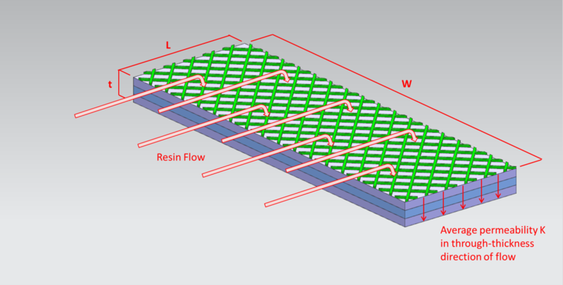
When external flow media is placed on the B-side surface of the part, its permeability—much lower than that of the reinforcement—causes resin to initially fill this layer. Once the external flow media layer is saturated, the resin flow shifts primarily to the through-thickness direction, as shown in the Figure below.
This change in flow direction modifies three terms in Darcy’s law:
- Cross-section area: The effective area becomes the surface area of the part, which is significantly larger than the cross-sectional area through the part.
- Infusion length: The infusion length is now the distance through the thickness of the part, which is generally significantly less than the length of the part in either in-plane direction.
- Permeability: The reinforcement permeability is now considered in the through-thickness direction. This permeability will not be the same as the in-plane permeability and may be higher or lower, depending on the reinforcement architecture.
These changes to the variables in Darcy’s law shows that a much higher flow velocity can be achieved by increasing the area and reducing the length. This method is commonly implemented to ensure wetout of reinforcements with low in-plane permeability. The through-thickness permeability of the reinforcements may still prevent successful infusion of the part. The vacuum source should be implemented in a way to prevent resin flow from short-circuiting through the external flow media and closing off the vacuum port prematurely. It is common to include materials that provide a vacuum path to the part’s perimeter, ensuring even vacuum distribution.
Internal flow media[edit | edit source]
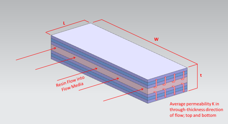
Internal flow media, unlike external media, remains within the part after curing. After filling the flow media layer, the resin flow transitions to through-thickness flow, but now splits into two directions, as seen in Figure below.
The key difference between internal and external flow media lies in the length variable of Darcy’s law. For internal flow media, the length of the infusion is reduced to half of the laminate stack in each direction. As the flow can move in two directions, this can potentially double the resin flow compared to the external media, reducing total fill time. For thick laminates, multiple layers of flow media may be incorporated to minimize the fill time.
Core Material[edit | edit source]
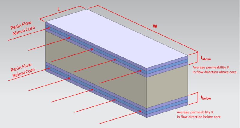
Core materials are widely used in composite components to provide additional stiffness at minimal weight. When evaluating the infusion of a sandwich panel, the flow above and below the core must be considered. This applies to each of the variables in Darcy’s law.
It is often more difficult to ensure proper flow is achieved beneath the core than above it. Different core features are available to promote flow on both sides or through the thickness of the core. This includes scored cores, where resin flow channels are scored into the surface of the core, and flexible cores, where the core is constructed from a group of individual core pieces held together by a fabric layer as seen in the Figure above.
In a layup where flow media is incorporated into the process to promote flow, there are design options that can assist with flow beneath the core. Flow media above the core can be cut to dimensions shorter than the edge of the core. Once the resin reaches the edge of the flow media, the laminate stack on top of the core has a much lower permeability. This change will result in the majority of new resin introduced to the system to flow beneath the core, assuming flow media is incorporated beneath the core as well.
| About | Help |
Welcome
Welcome to the CKN Knowledge in Practice Centre (KPC). The KPC is a resource for learning and applying scientific knowledge to the practice of composites manufacturing. As you navigate around the KPC, refer back to the information on this right-hand pane as a resource for understanding the intricacies of composites processing and why the KPC is laid out in the way that it is. The following video explains the KPC approach:
Understanding Composites Processing
The Knowledge in Practice Centre (KPC) is centered around a structured method of thinking about composite material manufacturing. From the top down, the heirarchy consists of:
- The factory
- Factory cells and/or the factory layout
- Process steps (embodied in the factory process flow) consisting of:
The way that the material, shape, tooling & consumables and equipment (abbreviated as MSTE) interact with each other during a process step is critical to the outcome of the manufacturing step, and ultimately critical to the quality of the finished part. The interactions between MSTE during a process step can be numerous and complex, but the Knowledge in Practice Centre aims to make you aware of these interactions, understand how one parameter affects another, and understand how to analyze the problem using a systems based approach. Using this approach, the factory can then be developed with a complete understanding and control of all interactions.
Interrelationship of Function, Shape, Material & Process
Design for manufacturing is critical to ensuring the producibility of a part. Trouble arises when it is considered too late or not at all in the design process. Conversely, process design (controlling the interactions between shape, material, tooling & consumables and equipment to achieve a desired outcome) must always consider the shape and material of the part. Ashby has developed and popularized the approach linking design (function) to the choice of material and shape, which influence the process selected and vice versa, as shown below:
Within the Knowledge in Practice Centre the same methodology is applied but the process is more fully defined by also explicitly calling out the equipment and tooling & consumables. Note that in common usage, a process which consists of many steps can be arbitrarily defined by just one step, e.g. "spray-up". Though convenient, this can be misleading.
Workflows
The KPC's Practice and Case Study volumes consist of three types of workflows:
- Development - Analyzing the interactions between MSTE in the process steps to make decisions on processing parameters and understanding how the process steps and factory cells fit within the factory.
- Troubleshooting - Guiding you to possible causes of processing issues affecting either cost, rate or quality and directing you to the most appropriate development workflow to improve the process
- Optimization - An expansion on the development workflows where a larger number of options are considered to achieve the best mixture of cost, rate & quality for your application.
To use this website, you must agree to our Terms and Conditions and Privacy Policy.
By clicking "I Accept" below, you confirm that you have read, understood, and accepted our Terms and Conditions and Privacy Policy.


